Silencing unit and internal-combustion engine exhaust silencer using same

A technology of muffler unit and muffler, which is applied in the direction of machines/engines, muffler devices, mechanical equipment, etc., can solve the problems of poor structure of exhaust muffler, deterioration of aerodynamic performance, loss of power consumption of internal combustion engine, etc., and achieve compact structure, reduced The effect of small air resistance and reducing dependence

Inactive Publication Date: 2011-11-23
陈尔斌
View PDF2 Cites 8 Cited by
  • Summary
  • Abstract
  • Description
  • Claims
  • Application Information

AI Technical Summary

Problems solved by technology

Since the silencing volume of the expansion chamber muffler is determined by the expansion ratio, and the silencing frequency characteristic is determined by the length of the expansion part, in order to obtain a large silencing volume and good spectral characteristics, the existing internal combustion engine exhaust mufflers are poor in structure ; Due to the expansion and contraction of the channel section, the expansion chamber muffler will increase the resistance loss, especially when the air velocity is high, the aerodynamic performance will deteriorate, and the labyrinth air flow path will also increase the air resistance, so the exhaust Large air resistance, poor aerodynamic performance, high exhaust back pressure of the internal combustion engine, resulting in loss of power consumption and increased fuel consumption of the internal combustion engine

Method used


Image

  • Silencing unit and internal-combustion engine exhaust silencer using same
  • Silencing unit and internal-combustion engine exhaust silencer using same
  • Silencing unit and internal-combustion engine exhaust silencer using same

Examples


Embodiment 1

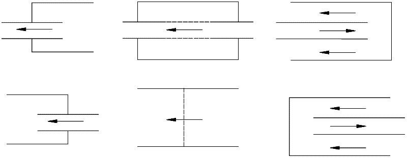
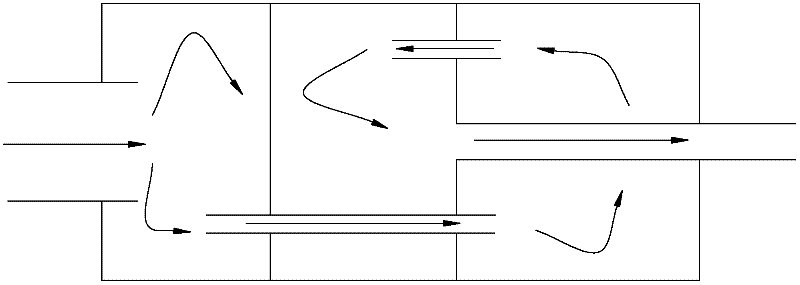
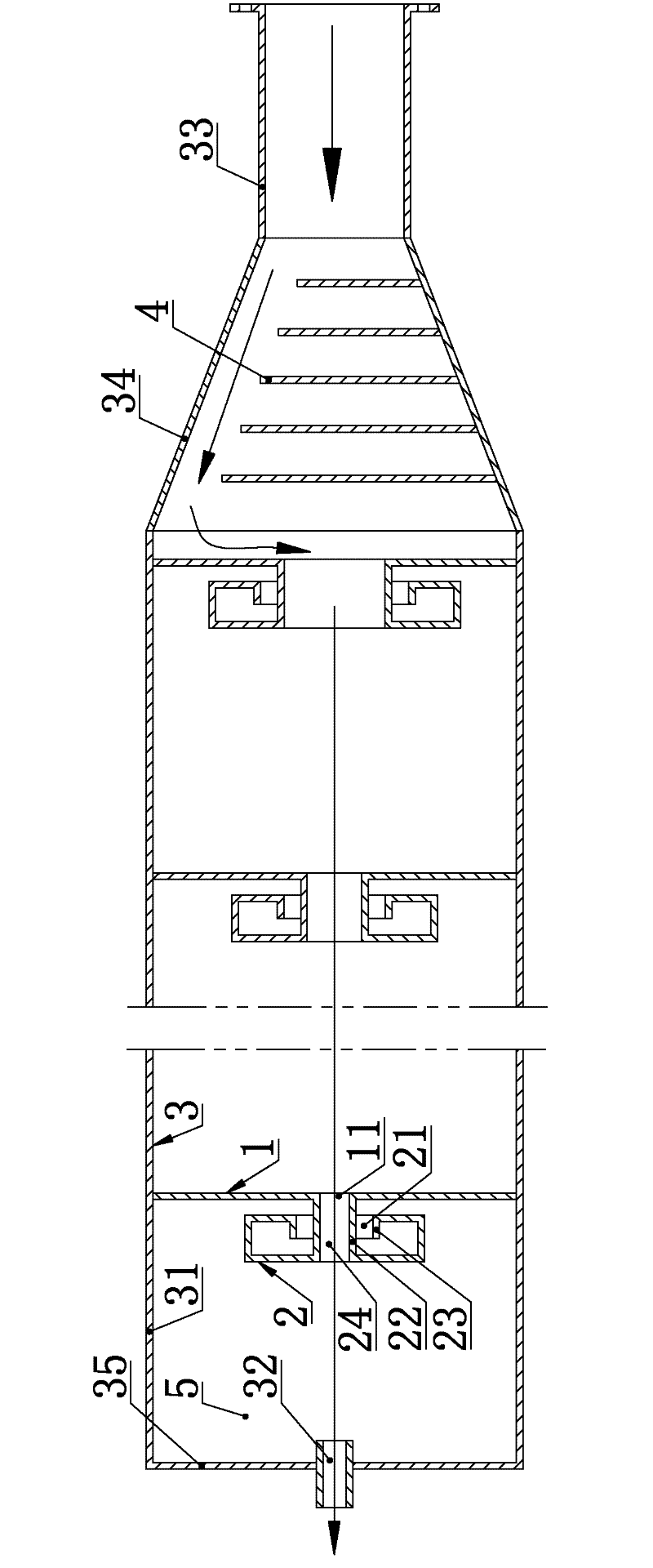
[0041] Such as image 3 , Figure 4 As shown, a kind of internal combustion engine exhaust muffler used for motorcycles includes a cylindrical cavity 5 surrounded by a muffler 3 housing 31, a muffler 3 inlet, and a muffler 3 outlet 32. There are five levels of muffler units inside, and the muffler units include partitions 1 and spiral structures 2 .

[0042] The partition 1 is a circular flat plate that is consistent with the radial section of the cavity 3 and vertical to the axial direction of the cavity 5. The surrounding of the partition 1 is fixedly connected with the housing 31 and axially partitions the cavity 5. coaxial through-hole. The through holes of the partitions 1 of each muffler unit are coaxial with the outlet 32 ​​of the muffler 3, and the air flow path is straight.

[0043] The plane square spiral coiled from the outside to the inside is used as the cross-section contour line. The cross-section contour line includes five sides and the angles between adjace...

Embodiment 2

[0048] Such as Figure 5 , Figure 6 As shown, an internal combustion engine exhaust muffler for motorcycles includes a cylindrical cavity 5 surrounded by a muffler 3 housing 31, a muffler 3 inlet, and a muffler 3 outlet 32, and the muffler 3 is axially installed in the cavity 5. There are five levels of noise reduction units, and the noise reduction units include partitions 1 and spiral structures 2 .

[0049] The partition 1 is an incomplete circular flat plate whose edge is composed of an arc and the chord between the two ends of the arc. The partition 1 is arranged perpendicular to the axial direction of the cavity 5 and axially partitions the cavity 5. The corresponding edge of the arc is fixedly connected with the shell 31, and the air channel 11 is formed by the radial gap between the corresponding edge of the chord and the shell 31. The radial gap corresponding to the adjacent partition 1 is radially symmetrical in the axial projection plane, and the airflow path Wav...

Embodiment 3

[0056] Such as Figure 7 As shown, an internal combustion engine exhaust muffler for motorcycles includes a cylindrical cavity 5 surrounded by a muffler 3 housing 31, a muffler 3 inlet, and a muffler 3 outlet 32, and a muffler unit is arranged in the cavity 5. The noise reduction unit includes a partition 1 and a spiral structure 2 .

[0057] The partition 1 is a spiral plate coiled axially along the cavity 5, and the width direction of the partition 1 is consistent with the radial direction of the cavity 5 and is smaller than the radius of the cavity 5; 12 is fixed on the housing 31; from the inlet to the outlet 32, the width of the partition 1 increases gradually, and the inner edge 13 of the partition 1 in the width direction is conical and spiral; between the adjacent circles of the partition 1 along the cavity 5 axial direction The gap between the gaps constitutes the helical air channel 11 that communicates with the cavities 5 at both axial ends of the partition plate 1...


PUM


Abstract

The invention relates to noise control, and provides a silencing unit. The silencing unit comprises a cavity, a partition plate, and an air passage for communicating two sides of the partition plate; the downstream lateral surface of the partition plate is provided with a spiral structure; by using a planar spiral line as a section contour line, a random section of the spiral structure is adapted with the section contour line, and the integral spiral structure is adapted with the shape formed when the section contour line moves along a locus line; and the spiral structure and the adjacent structure form the spiral silencing cavity and the opening thereof by encircling, and the opening is positioned in the propagation direction of sound wave reflected by the adjacent structure at the downstream side of the partition plate. Through the spiral structure, the reflecting probability is increased, the sound wave is captured, attenuation of the sound wave is increased, the silencing quantity is irrelevant with the expansion ratio, and the silencing and structural properties are better. The invention also provides an internal-combustion engine exhaust silencer. By adopting the silencing unit, good silencing and structural properties are ensured; and meanwhile, the upstream side of a random point on the airflow path is positioned at the inlet side of the silencer of the point, and the downstream side of the point is positioned at the outlet side of the silencer of the point, so the power performance of the air is good.

Description

technical field [0001] The invention relates to noise control, in particular to a muffler unit and an internal combustion engine exhaust muffler using the muffler unit. Background technique [0002] The muffler is a device for reducing airflow noise. It is installed in the pipeline or on the inlet and exhaust ports. It has a certain effect on noise reduction when the airflow passes through. Its performance mainly includes three aspects: 1. Noise reduction performance, including noise reduction The size and spectrum characteristics of the sound volume; 2. Aerodynamic performance, usually expressed by the full pressure difference between the inlet and outlet of the muffler; 3. Structural performance, which refers to its overall size, firmness, maintenance requirements, service life, etc. Evaluating the performance of the above three aspects of the muffler is both interrelated and mutually restrictive. From the perspective of the muffler's muffler performance, the greater the m...

Claims


Application Information

Patent Timeline
Patent Type & Authority Applications(China)
IPC IPC(8): F01N1/12F01N1/06
Inventor 陈尔斌
Owner 陈尔斌
Why Eureka
Try Eureka