
Principal focus type refracting-reflecting optical system

An optical system and light beam technology, applied in the field of optical systems, can solve the problems of difficult processing and detection of large-diameter high-order aspheric surfaces, complex correction groups, difficult manufacturing and processing, etc., and achieve good optical processing performance, convenient processing and inspection, and simple structure. Effect

Inactive Publication Date: 2013-03-20
INST OF OPTICS & ELECTRONICS - CHINESE ACAD OF SCI
View PDF3 Cites 0 Cited by
  • Summary
  • Abstract
  • Description
  • Claims
  • Application Information

AI Technical Summary

Problems solved by technology

[0003] The traditional large-aperture telescope must use a reflective primary mirror, and the characteristics of the reflective optical system limit the increase of the field of view. Although there are several special forms that can achieve a larger field of view, such as the Schmidt telescope and the three-dimensional Anti-even four anti-telescopes, but because the Schmidt correction plate is difficult to manufacture and process, and the three-anti or four-anti-telescopes have a large block, so their serious defects have led to seldom used in practice
The prime-focus catadioptric optical system can theoretically achieve a larger field of view, but the correction group is more complicated, requiring the use of various grades of optical glass for achromatization, and the use of high-order aspheric surfaces to correct aberrations. For large-diameter optical lenses In other words, many grades of optical glass are difficult to refine, and there are certain difficulties in the processing and testing of large-aperture and high-order aspheric surfaces. Therefore, it is necessary to develop a prime-focus optical system that is convenient for engineering realization.

Method used


Image

  • Principal focus type refracting-reflecting optical system
  • Principal focus type refracting-reflecting optical system
  • Principal focus type refracting-reflecting optical system

Examples


Embodiment Construction

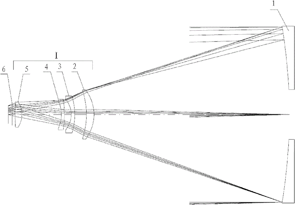
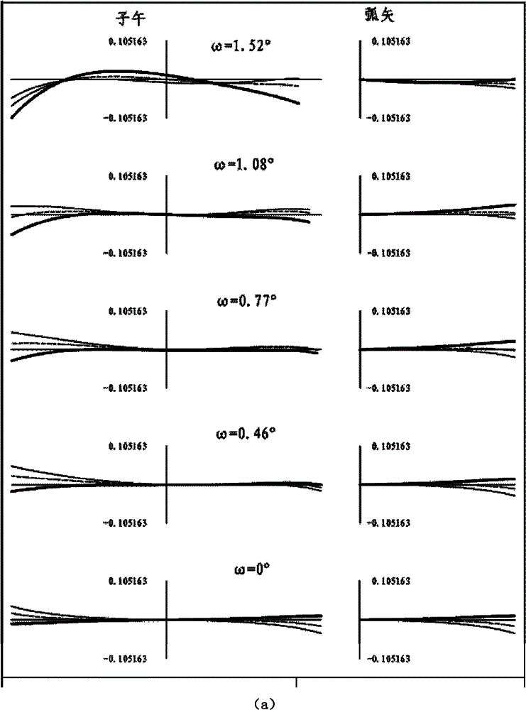
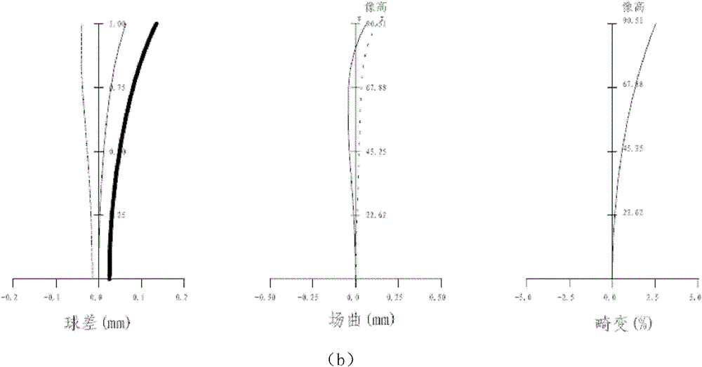
[0015] see figure 1 , the main focus type catadioptric optical telescope of the present invention comprises a parabolic primary mirror 1 and a correction group 1 and a focal plane shutter 6, wherein the first lens 2, the second lens 3, the third lens 4 and the fourth lens 5 are formed The correction group I is placed on the reflected optical path of the main mirror 1, and the correction group I mainly corrects the aberration of the peripheral field of view of the main mirror 1, thereby increasing the effective field of view. Among them, the characteristics and positional relationship of the four lenses of the correction group I according to the optical path are as follows: the first lens 2 is a meniscus lens with a positive refractive power and a convex surface facing the main mirror 1, and the second lens 3 is a negative refractive power and a convex surface. A meniscus lens facing the main mirror 1 , the third lens 4 is a meniscus lens with a negative refractive power and a ...


PUM


Abstract

The invention relates to a principal focus type refracting-reflecting optical system having an aperture of above 1m, a viewing field of above 3 degrees and a flat image surface, which is convenient for being externally connected with a focal plane photoelectric receiving device and can be used for ground-based observation. The principal focus type refracting-reflecting optical system comprises a paraboloidal primary lens (1), a correction group (2) and a focal plane shutter (6), wherein the correction group comprises four correction lenses which are a first lens (2) having positive focal power and being a meniscus lens with a convex surface facing the primary lens, a second lens (3) having negative focal power and being a meniscus lens with a convex surface facing the primary lens, a third lens (4) having negative focal power and being a meniscus lens with a convex surface facing the primary lens and a fourth lens (5) having positive focal power respectively. In the correction group (1), only the concave surface of the first lens (2) is a paraboloid, the concave surfaces of other lenses are spherical surfaces.

Description

technical field [0001] The invention relates to the field of optical systems, in particular to a prime-focus type catadioptric optical telescope, which can be applied to a large field-of-view field-based telescope with an aperture exceeding 1m. Background technique [0002] The flat-field telescope with large aperture and large field of view is of great significance in astronomical observation and space debris monitoring. Large aperture means stronger light-gathering ability, thus detecting weaker magnitudes; large field of view means larger single-frame field of view, which can search the sky faster; flat field means convenient configuration Focal plane photodetection device. Large-aperture and large-field-of-view flat-field telescopes are playing an increasingly important role in sky surveys and space debris monitoring. [0003] The traditional large-aperture telescope must use a reflective primary mirror, and the characteristics of the reflective optical system limit th...

Claims


Application Information

Patent Timeline
Patent Type & Authority Patents(China)
IPC IPC(8): G02B17/08G02B23/00
Inventor 向贤毅马文礼
Owner INST OF OPTICS & ELECTRONICS - CHINESE ACAD OF SCI
Learn More