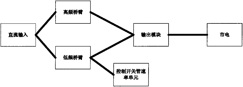
Transformer-free unilateral inductor grid-connected inverter circuit
A technology of inverter circuit and transformer, applied in the field of unilateral inductance grid-connected inverter circuit, can solve the problems of electromagnetic interference, large common mode current, heavy weight, etc., and achieve the effect of good electromagnetic compatibility, small components and low cost
- Summary
- Abstract
- Description
- Claims
- Application Information
AI Technical Summary
Problems solved by technology
Method used
Image

Examples
Embodiment 1
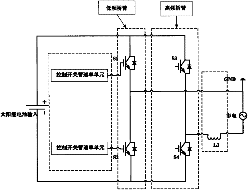
[0036] The two high-frequency switch tubes S3, S4 and the two low-frequency switch tubes S1, S2 respectively use insulated gate bipolar transistors (IGBTs), and their circuit principles are as follows: figure 2 As shown, the emitter of the switching tube S3 is connected to the collector of the switching tube S4, the collector of the switching tube S3 is connected to the positive pole of the solar cell input, and the emitter of the switching tube S4 is connected to the negative pole of the solar cell input. The emitter of the switch tube S1 is connected to the collector of the switch tube S2, the collector of the switch tube S1 is connected to the anode of the solar cell input and also connected to the collector of the switch tube S3, the emitter of the switch tube S2 is connected to the solar cell The negative electrode of the input is also connected to the emitter of the switch tube S4, and the gates of the two low-frequency switch tubes S1 and S2 are respectively connected t...
Embodiment 2
[0047] The two high-frequency switch tubes S3, S4 and the two low-frequency switch tubes S1, S2 respectively use power field effect transistors (MOSFETs). The circuit principle is shown in Figure 11, where the source of the switch tube S3 and the drain of the switch tube S4 The drain of the switching tube S3 is connected to the positive pole of the solar battery input, and the source of the switching tube S4 is connected to the negative pole of the solar battery input. The source of the switching tube S1 is connected to the drain of the switching tube S2, the drain of the switching tube S1 is connected to the positive pole of the solar cell input and also connected to the drain of the switching tube S3, the source of the switching tube S2 is connected to the solar cell The negative electrode of the input is also connected to the source of the switching tube S4, and the gates of the two low-frequency switching tubes S1 and S2 are respectively connected to the speed control unit ...
PUM
 Abstract
Description
Claims
Application Information
 - Generate Ideas
- Intellectual Property
- Life Sciences
- Materials
- Tech Scout
- Unparalleled Data Quality
- Higher Quality Content
- 60% Fewer Hallucinations
Browse by: Latest US Patents, China's latest patents, Technical Efficacy Thesaurus, Application Domain, Technology Topic, Popular Technical Reports.
© 2025 PatSnap. All rights reserved.Legal|Privacy policy|Modern Slavery Act Transparency Statement|Sitemap|About US| Contact US: help@patsnap.com