Coreless permanent magnet linear motor with cooling structure, manufacturing mould for winding coil thereof and machining process for winding coil

A permanent magnet linear motor and cooling structure technology, applied in the direction of electric components, manufacturing motor generators, magnetic circuit shape/style/structure, etc., to achieve the effect of simple structure, easy manufacture, neat and beautiful appearance

Active Publication Date: 2011-11-23
HARBIN INST OF TECH
View PDF5 Cites 11 Cited by
  • Summary
  • Abstract
  • Description
  • Claims
  • Application Information

AI Technical Summary

Problems solved by technology

[0004] The present invention aims to solve the heat dissipation problem of the coreless permanent magnet linear motor, and provides a coreless permanent magnet linear motor with a cooling structure and a manufacturing mold and winding coil processing technology of the winding coil

Method used


Image

  • Coreless permanent magnet linear motor with cooling structure, manufacturing mould for winding coil thereof and machining process for winding coil
  • Coreless permanent magnet linear motor with cooling structure, manufacturing mould for winding coil thereof and machining process for winding coil
  • Coreless permanent magnet linear motor with cooling structure, manufacturing mould for winding coil thereof and machining process for winding coil

Examples


specific Embodiment approach 1

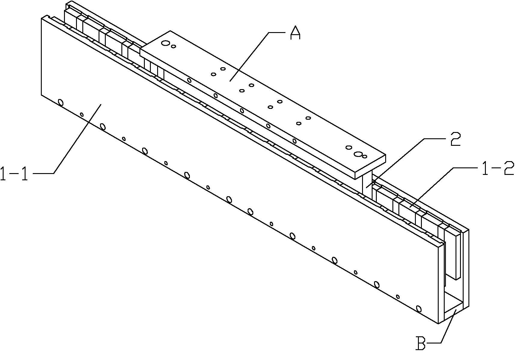
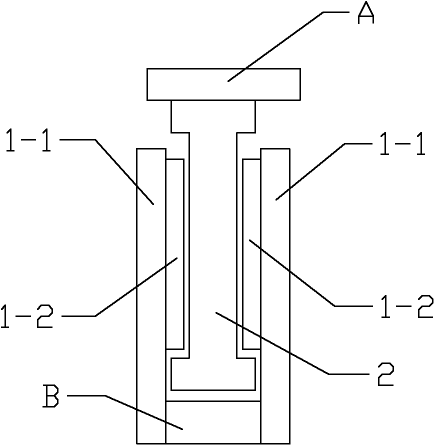
[0031] Specific implementation mode one: the following combination Figure 1 to Figure 5 Describe this embodiment. This embodiment includes a stator with a double-sided structure and a mover 2. The stator is arranged on both sides of the mover 2 in mirror image symmetry. The stator includes a stator yoke 1-1 and NS-level permanent magnets 1-2 staggered. , an air gap is formed between the stator and the mover 2,

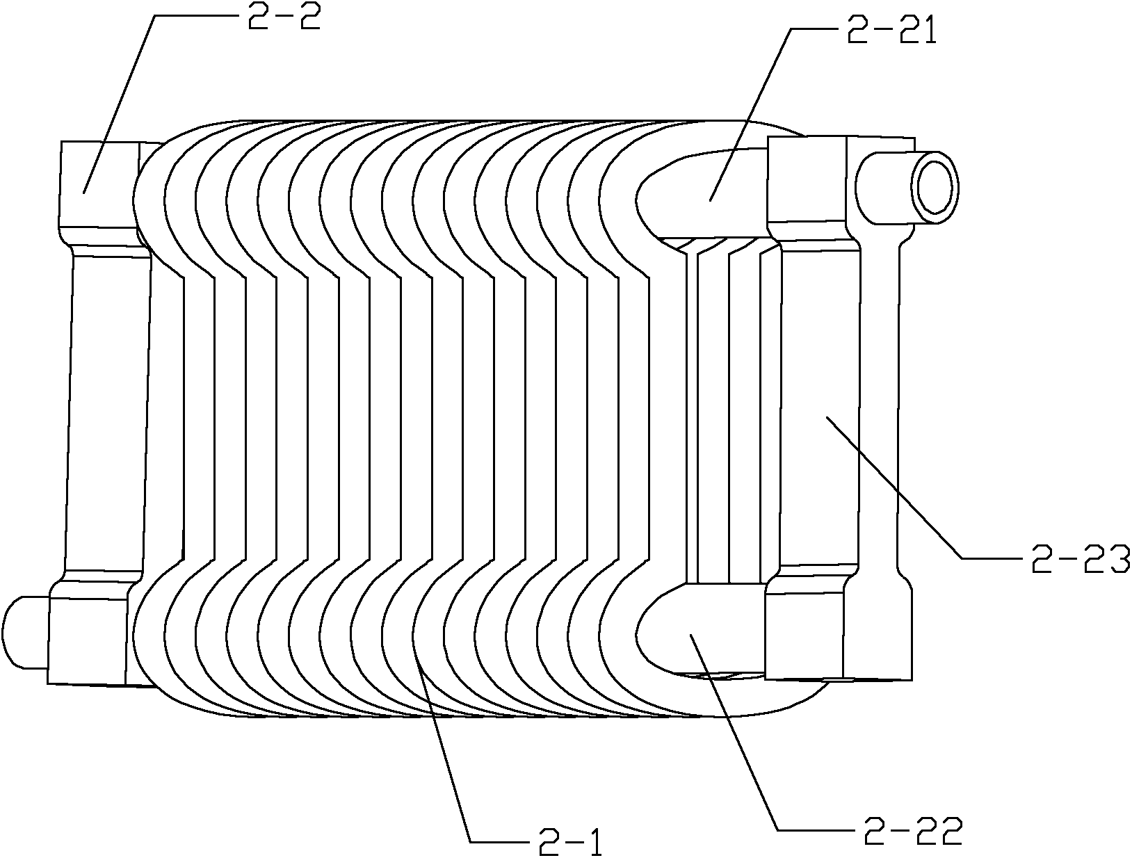
[0032] The mover 2 includes an armature winding 2-1 and a cooling pipeline 2-2. The armature winding 2-1 is a double-layer non-overlapping fractional slot concentrated winding. The upper end and the lower end of the armature winding 2-1 are arc-shaped. The upper end and the lower end of the armature winding 2-1 are formed with arc-shaped through holes along the moving direction, and the cross section of the armature winding 2-1 is I-shaped along the direction perpendicular to the moving direction.

[0033] The cooling pipeline 2-2 is composed of an upper pipeline 2-2...

specific Embodiment approach 2

[0040] Specific implementation mode two: the following combination Figure 3 to Figure 5 This embodiment is described. This embodiment is a further description of Embodiment 1. Both the upper pipeline 2-21 and the lower pipeline 2-22 in this embodiment are in close contact with the inner surface of the end of the armature winding 2-1. catch.

specific Embodiment approach 3

[0041] Embodiment 3: This embodiment is a further description of Embodiment 1 or 2, and the span of the armature winding 2-1 is one virtual slot.


PUM


Abstract

The invention relates to a coreless permanent magnet linear motor with a cooling structure, a manufacturing mould for a winding coil thereof and a machining process for the winding coil and belongs to the technical field of linear motors. The coreless permanent magnet linear motor with the cooling structure is used for solving the radiation problem of a coreless permanent magnet linear motor. Stators of the coreless permanent magnet linear motor with the cooling structure are mirror-symmetrically arranged at the two sides of a rotor, wherein the rotor comprises an armature winding and a cooling pipeline; the cooling pipeline is composed of an upper pipeline, a lower pipeline and two connectors; the upper pipeline passes through an arc-shaped through hole which is formed on the upper end part of the armature winding; and the lower pipeline passes through an arc-shaped through hole which is formed on the lower end part of the armature winding. The manufacturing mould for the winding coil of the coreless permanent magnet linear motor with the cooling structure is composed of two winding shape-fixing components, a coil dislocation moving component and two base plates. The machining process for the winding coil by using the manufacturing mould for the winding coil is used for realizing the dislocation of upper and lower coil edges of the winding coil and preventing a winding from falling into pieces. The machining process provided by the invention is suitable for the coreless permanent magnet linear motor.

Description

technical field [0001] The invention relates to a coreless permanent magnet linear motor with a cooling structure and a manufacturing mold for its winding coils and a processing technology for the winding coils, belonging to the technical field of linear motors. Background technique [0002] Coreless permanent magnet linear synchronous motors are widely used in high-speed and high-precision small and medium-sized CNC machine tools, electronics manufacturing industry, and micro-nano technology manufacturing. It can achieve high positioning accuracy and system resolution. Usually, the thermal resistance of the coreless linear motor is large, and the heat generated by the copper loss of its winding is dissipated to the external system through heat transfer. In the field of ultra-precision machine tool processing and micro-nano technology manufacturing, thermal expansion will adversely affect the accuracy of the motor itself and the entire system. Adding a cooling structure ins...

Claims


Application Information

Patent Timeline
Patent Type & Authority Applications(China)
IPC IPC(8): H02K41/02H02K3/12H02K1/32H02K15/09
Inventor 李立毅唐勇斌潘东华寇宝泉
Owner HARBIN INST OF TECH
Why Eureka
Try Eureka