Optical fiber interface of flat-panel television and signal transmission method thereof

A flat-panel TV, optical fiber interface technology, applied in the field of signal transmission interface and signal transmission, can solve the problems of complex noise crosstalk and radiation, complex twisted pair connection of transmission medium, unfavorable reliability and manufacturability of the whole machine, etc. complex effects

Inactive Publication Date: 2011-11-23
TCL CORPORATION +1
View PDF5 Cites 7 Cited by
  • Summary
  • Abstract
  • Description
  • Claims
  • Application Information

AI Technical Summary

Problems solved by technology

[0004] 1. The twisted pair connection of the transmission medium is complicated. Taking the current 120Hz LCD screen as an example, to transmit a 1920x1080 high-definition signal, 4 channels of LVDS, 20 pairs of twisted pairs (40 lines), and other connections such as power ground are required , a total of more than 70 lines; if it is a 240Hz LCD screen, the number of connection lines will be doubled, so many connection lines are not conducive to the reliability and manufacturability of the whole machine, and are also not conducive to the ultra-thin design of flat-panel TVs;
[0005] 2. The LVDS level cannot directly drive the LCD screen, and level conversion is required;
[0006] 3. Electro Magnetic Compatibility (EMC) for high-speed transmission. With the high-definition screen and frequency multiplication drive, the amount of transmitted data has increased dramatically. Such complicated connectors and wire connections will cause noise crosstalk and EMC issues such as radiation become more complex

Method used


Image

  • Optical fiber interface of flat-panel television and signal transmission method thereof
  • Optical fiber interface of flat-panel television and signal transmission method thereof
  • Optical fiber interface of flat-panel television and signal transmission method thereof

Examples


Embodiment Construction

[0025] In order to make the object, technical solution and advantages of the present invention clearer, the present invention will be further described in detail below in conjunction with the accompanying drawings and embodiments. It should be understood that the specific embodiments described here are only used to explain the present invention, not to limit the present invention.

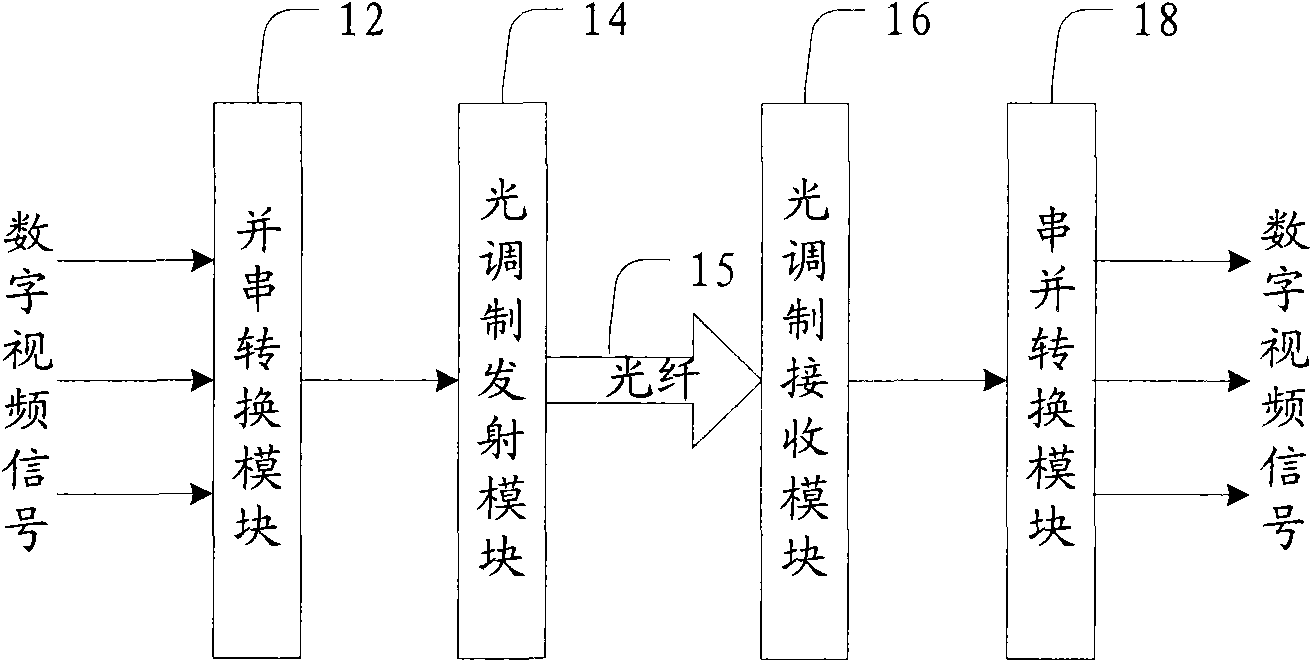
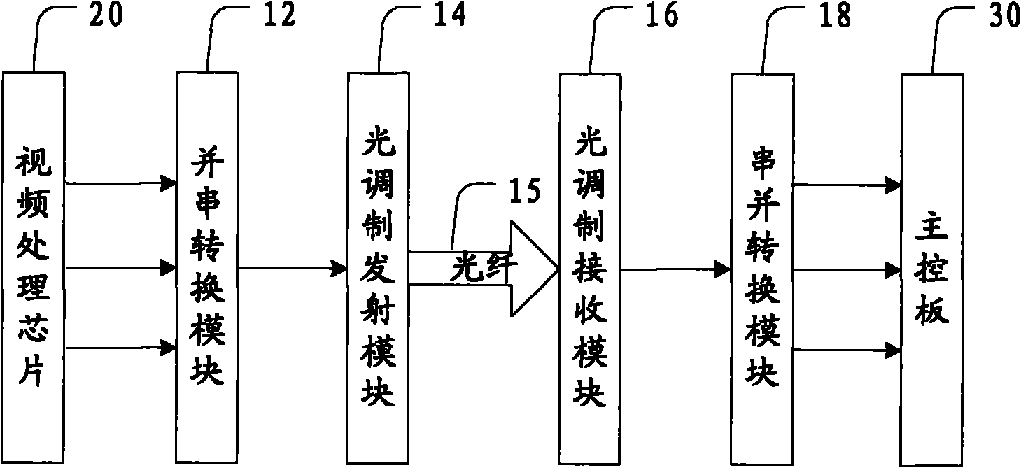
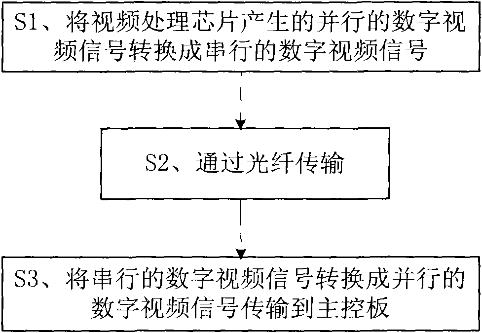
[0026] The technical solution provided by the present invention is: the parallel digital video signal at the sending end of the main board in the flat-panel TV is converted through parallel to serial, modulated and transmitted through the optical fiber, and the modulated signal transmitted through the optical fiber is received and demodulated at the receiving end of the LCD screen in the flat-panel TV. Then restore the original parallel digital signal through serial-to-parallel conversion, in which, the transmission and reception of the digital video signal are only connected by one optical fiber. ...


PUM


Abstract

The invention provides an optical fiber interface of a flat-panel television. The optical fiber interface comprises a parallel/serial conversion module, an optical modulation transmission module, an optical fiber, an optical receiving demodulation module and a deserialization module, wherein the parallel/serial conversion module converts a received parallel digital video signal into a serial digital video signal and transmits the serial digital video signal to the optical modulation transmission module; the optical modulation transmission module performs modulation transmission on the received signal; the optical fiber transmits an optical fiber signal output by the optical modulation transmission module as a transmission medium; the optical receiving demodulation module receives the optical fiber signal from the optical fiber and demodulates the optical fiber signal; and the deserialization module deserializes the demodulated signal and recovers the parallel digital video signal. The optical fiber interface of the flat-panel television transmits the digital video signal by the optical fiber to effectively solve the problems of complexity in connection between a liquid crystal screen and a main board in the flat-panel television, limitations to a transmission rate, electromagnetic compatibility and help to develop ultrathin, modular and high-definition flat-panel televisions.

Description

technical field [0001] The invention relates to the technical field of flat-panel televisions, in particular to a signal transmission interface and a signal transmission method of the flat-panel television. Background technique [0002] At present, the signal interface between the motherboard and the LCD screen in a flat-panel TV is usually a low-voltage differential signaling interface (Low-Voltage Differential Signaling, LVDS), and the transmission medium is a balanced cable (such as a twisted pair). Excellent characteristics of low power consumption, low noise and low cost. [0003] However, the existing transmission interface and transmission medium still have deficiencies: [0004] 1. The twisted pair connection of the transmission medium is complicated. Taking the current 120Hz LCD screen as an example, to transmit a 1920x1080 high-definition signal, 4 channels of LVDS, 20 pairs of twisted pairs (40 lines), and other connections such as power ground are required , a ...

Claims


Application Information

Patent Timeline
Patent Type & Authority Applications(China)
IPC IPC(8): H04N7/22
Inventor 宋永红杨福军张晓东谢仁礼
Owner TCL CORPORATION
Why Eureka
Try Eureka