An air cooling device matched with drying equipment

A technology of air cooling device and drying equipment, which is applied in drying, lighting and heating equipment, drying solid materials, etc.

Inactive Publication Date: 2011-11-30
王远大
View PDF5 Cites 6 Cited by
  • Summary
  • Abstract
  • Description
  • Claims
  • Application Information

AI Technical Summary

Problems solved by technology

Therefore, the lignite drying process using flue gas as the drying medium generally only removes the free water (external water) of lignite.

Method used


Image

  • An air cooling device matched with drying equipment
  • An air cooling device matched with drying equipment

Examples


Embodiment 1

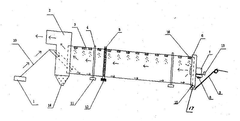
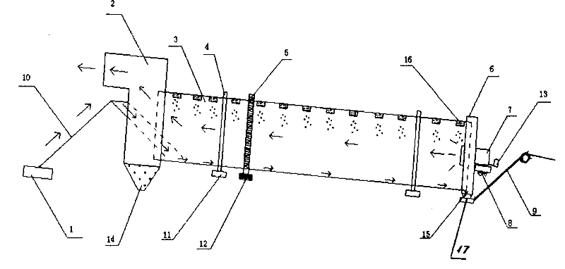
[0014] Example 1: Combining figure 1 , the present invention is an air-cooling device matched with drying equipment, which is composed of a feeding unit, a rotating drum unit, a discharging unit, a cold air supply unit and a bearing unit, the feeding unit is connected with the rotating drum unit, and the rotating The drum unit is connected to the cold air supply unit, the discharge unit and the carrying unit; the feed unit includes a feeding conveyor (1) and a feeding conveyor belt (10), and the feeding conveyor (1) is connected to the feeding conveyor belt (10 ), the rotary drum unit includes a heat exhaust dust outlet (2), a dust storage bucket (14), a rotary drum (3), a lifting plate (16), a closed port at the end of the drum (6) and The installation inclination angle between the discharge hopper (15), the rotary drum (3) and the ground is 3° to 5°, the origin of the inclination angle is located at the tail of the rotary drum (3), and the heat and dust outlet (2) is connect...

Embodiment 2

[0021] Example 2: Combining figure 1 , the working process of the present invention is as follows: the material in the hot state (the material described in this embodiment is lignite) dried by the drying equipment is input to the rotary drum unit by the feeding unit, and is passed through the rotary drum (3) The lifting plate (16) inside lifts the material continuously from the upper part of the rotary drum (3). The cold air blown into the cold air nozzle (7) will air-cool the tumbled and lifted materials. During the air-cooling process, some dust enters the dust storage hopper (14) and is recovered, and the rest of the flue gas dust passes through the heat exhaust dust outlet ( 2) Enter the dust removal equipment for purification and separation. The rotary drum (3) relies on the roller belt embedded in the outside to carry the load through the rollers (11) installed on the base. The bull gear (5) embedded in the outer side of the rotary drum (3) meshes with the pinion of th...


PUM


Abstract

The invention provides an air cooling device matched with drying equipment. The feeding unit is connected to the rotating drum unit, and the rotating drum unit is connected to the cold air supply unit, the discharging unit and the carrying unit; the feeding conveyor is connected to the feeding conveyor belt, and the heat and dust discharge port is connected to the dust storage hopper and the rotating drum. The installation inclination angle between the type drum and the ground is 3° to 5°, the discharge conveyor is connected to the discharge conveyor belt, the cold air supply nozzle is connected to the fan, the fan is connected to the motor, the roller belt is connected to the roller, and the large gear is connected to the gear transmission combination. The lifting plate installed in the rotary drum continuously lifts the material to be refrigerated from top to bottom, and receives the cold air sent by the tail fan for cooling, so that the material reaches a condensed state. The invention adopts the principle of air cooling to cool down the lignite and dust with high temperature and recover the dust, so that there is no fire and no dust during transportation, and the environmental protection and low carbon meet the standard.

Description

(1) Technical field [0001] The invention relates to coal mechanical equipment, in particular to an air cooling device matched with drying equipment. (2) Background technology [0002] There are many capillary pores inside the lignite, and the wet lignite is like a sponge that absorbs enough water; while the dry (referring to the situation where only surface water is removed) lignite is like a wrung-out sponge. When the lignite after drying (referring to the situation that only removes surface water) encounters water, it will absorb moisture, the same reason as a wrung-out sponge absorbs water. This is why lignite after drying (referring to the situation where only surface water has been removed) will absorb moisture when left for too long or during transportation. When the lignite is heated above 100 degrees at room temperature, most of the free water can be evaporated. When the lignite moisture is lower than 15%, if it is necessary to continue drying and dehydration, that ...

Claims


Application Information

Patent Timeline
Patent Type & Authority Applications(China)
IPC IPC(8): F26B25/00
Inventor 王远大
Owner 王远大
Why Eureka
Try Eureka