Carbon Reduction Method for Coal-fired Power Plant Tail Gas Emission Reduction

A coal-fired power plant, exhaust gas technology, applied in the direction of separation methods, chemical instruments and methods, air quality improvement, etc., to achieve the effects of reducing environmental protection costs, saving natural gas, and saving environmental protection costs

Inactive Publication Date: 2011-12-07
TIANJIN UNIV
View PDF2 Cites 5 Cited by
  • Summary
  • Abstract
  • Description
  • Claims
  • Application Information

AI Technical Summary

Problems solved by technology

[0008] CO currently used by the chemical industry 2 The total is 115 million tons, accounting for only the CO emitted to the atmosphere each year 2 about 0.5% of the total, although the CO 2 Techniques such as injection into oil we

Method used


Image

  • Carbon Reduction Method for Coal-fired Power Plant Tail Gas Emission Reduction
  • Carbon Reduction Method for Coal-fired Power Plant Tail Gas Emission Reduction
  • Carbon Reduction Method for Coal-fired Power Plant Tail Gas Emission Reduction

Examples


Embodiment 1

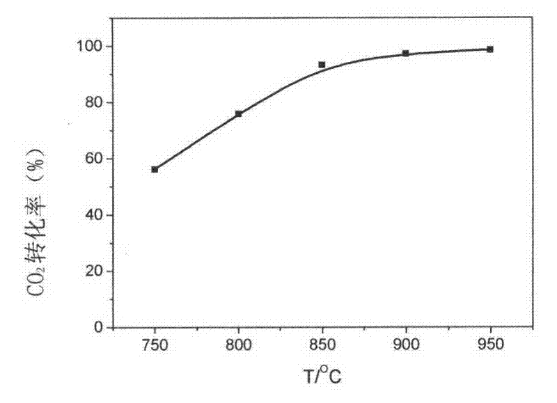
[0035] Using corn cob charcoal as raw material, simulated laboratory flue gas (CO 2 Content 10.13%, SO 2 Content 1500ppm, NO content 360ppm, the rest is N 2 ) for carbon reduction experiments. figure 2 CO in flue gas was simulated for corncob charcoal reduction reaction at different temperatures (750°C, 800°C, 850°C and 950°C). 2 The conversion rate of CO at 950°C 2 The conversion rate can reach 99%, and almost all of them are converted into CO.

[0036] 1. Gas heating up

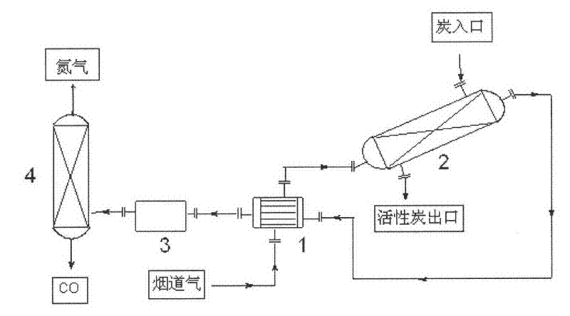
[0037] The 500°C power plant tail gas enters the heat exchanger to exchange heat with the reactor outlet gas, and then enters the preheating section of the reactor to raise the temperature to 950°C required for the carbon reduction reaction.

[0038] 2. Reduction reaction

[0039] The carbon dioxide in the tail gas fully reacts with the charcoal filled in the reactor to generate carbon monoxide, and a small amount of SO in the tail gas is also reduced in the reactor 2 and NOx. During the reaction p...

Embodiment 2

[0046] Using coconut shell charcoal as raw material, simulated laboratory flue gas (CO 2 Content 10.13%, SO 2 Content 1500ppm, NO content 360ppm, the rest is N 2 ) to carry out the charcoal reduction experiment, and the operation steps are the same as in Example 1.

Embodiment 3

[0048] Using coke as raw material, simulated laboratory flue gas (CO 2 Content 10.13%, SO 2 Content 1500ppm, NO content 360ppm, the rest is N 2 ) to carry out the charcoal reduction experiment, and the operation steps are the same as in Example 1.

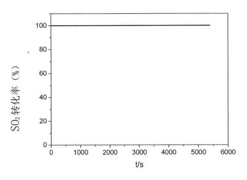
[0049] image 3 and Figure 4 shows that at 950°C SO 2 and NO are completely converted. Figure 5 Simulated CO in flue gas when coconut shell charcoal was subjected to carbon reduction reaction at different temperatures (750°C, 800°C, 850°C and 950°C). 2 The conversion rate of CO at 950°C 2 The conversion rate can reach 98.1%. Similarly, at this temperature, SO 2 and NO conversions are 100%, with image 3 and Figure 4 The results are exactly the same.


PUM


Abstract

The invention relates to a carbon reduction method for tail gas emission reduction of a coal-fired power plant, which mainly includes the steps of gas heating, carbon reduction reaction, gas cooling and gas separation. The method of converting CO2 into CO to reduce carbon dioxide emissions not only avoids the huge cost of carbon dioxide capture, transportation and landfill, but also produces CO as an important raw material for one-carbon chemical industry, which has good economic benefits and can Save a lot of gas. During the carbon reduction process, the sulfur and nitrogen oxides in the flue gas are reduced to elemental sulfur and nitrogen, and the decarbonization, desulfurization and denitrification of the flue gas are realized simultaneously, which greatly reduces the environmental protection cost of the power plant. The invention can meet the needs of carbon emission reduction in industries such as power generation, cement, steel and oil refining, especially the control and utilization of carbon dioxide emission from tail gas of coal-fired power plants.

Description

technical field [0001] The invention relates to a carbon reduction method for tail gas emission reduction of coal-fired power plants, which can meet the needs of carbon emission reduction in industries such as power generation, cement, steel and oil refining, especially the control and utilization of carbon dioxide emissions from the tail gas of coal-fired power plants. Background technique [0002] According to the World Coal Institute report, coal is vital to the world's electricity supply. 41% of the world's electricity is provided by coal, and in some countries the proportion is even higher, as shown in Table 1 [http: / / www.worldcoal.org / coal / uses-of-coal / coal-electricity / ] . The importance of coal to electricity supply will continue to increase, and by 2030 the proportion of global coal power will be 44%. Coal happens to be the fossil fuel with the most carbon content, and the carbon dioxide released by burning coal accounts for 40% of the total carbon dioxide released...

Claims


Application Information

Patent Timeline
IPC IPC(8): B01D53/81B01D53/62B01D53/60
CPCY02A50/20
Inventor 周理苏伟孙艳周亚平
Owner TIANJIN UNIV
Why Eureka
Try Eureka