Sludge Dehydrator

A technology of sludge dewatering machine and sludge pump, which is applied in the direction of dehydration/drying/concentrated sludge treatment, etc., which can solve the problems of odor emission, difficulty in maintaining the pressure of the filter chamber, poor sealing reliability of the filter chamber, etc., and achieve discharge The effect of short time, short path, and small discharge resistance

Active Publication Date: 2011-12-07
安徽省通源环境节能股份有限公司
View PDF9 Cites 13 Cited by
  • Summary
  • Abstract
  • Description
  • Claims
  • Application Information

AI Technical Summary

Problems solved by technology

[0002] At present, domestic sludge dewatering technology and equipment are mainly belt filter presses and centrifugal dehydrators, and there are also a small number of traditional plate and frame filter presses, which can only dehydrate concentrated sludge with a moisture content of more than 93% to a moisture content of 75-85%, the existing problems of sludge with a moisture content of 75-85% are: inconvenient transportation and high cost, large stacking area, and cannot be directly disposed of at all, sludge contains a large amount of organic matter and rich nitrogen, phosphorus, potassium, etc. Nutrients, which are perishable, produce stench and breed mosquitoes and flies, and the resulting stench causes secondary pollution; they cannot be directly disposed of, and must be reprocessed before they can be landfilled or utilized, while thermal energy treatment is costly and easy to produce odor emissions, etc. Secondary pollution
[0003] At present, the ordinary plate and frame filter press, diaphragm plate and frame filter press and sludge deep dewatering filter press will filter out a large amount of sludge in the process of forming a mud cake

Method used


Image

  • Sludge Dehydrator
  • Sludge Dehydrator
  • Sludge Dehydrator

Examples


Embodiment Construction

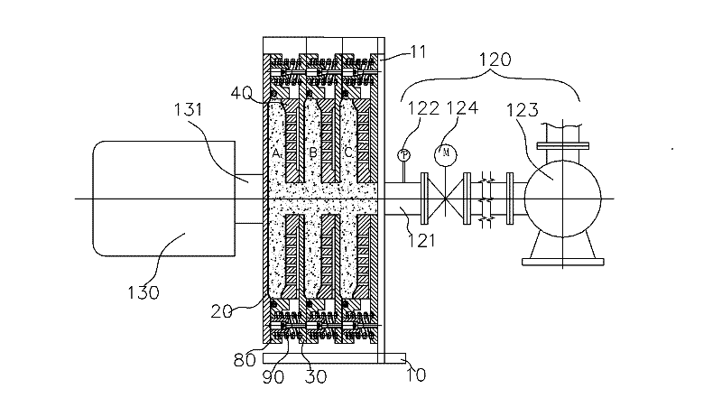
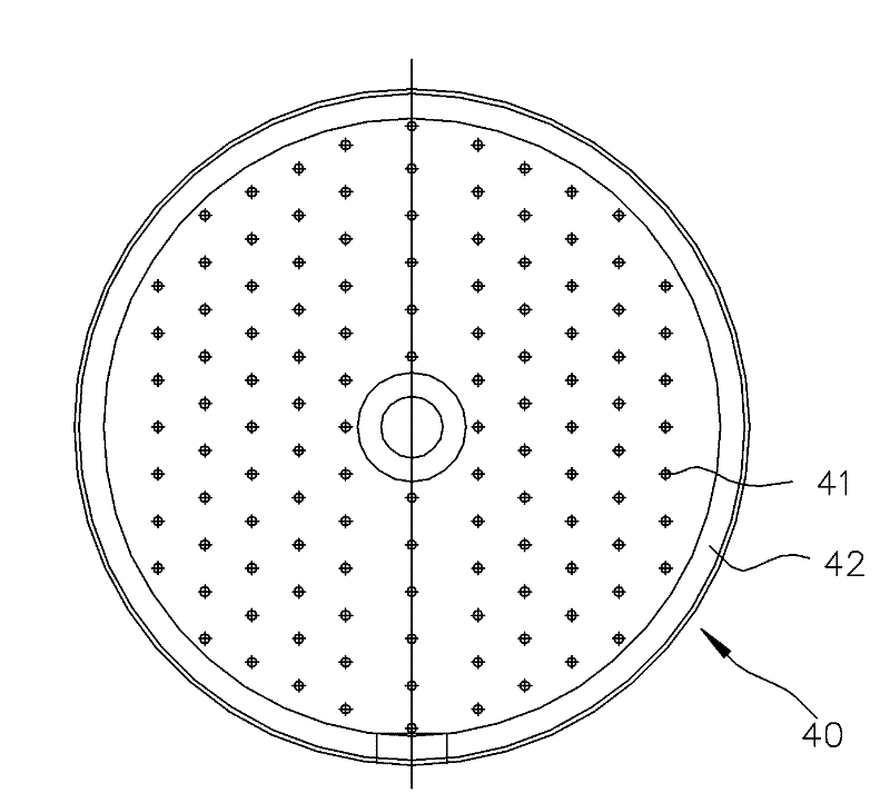
[0011] Such as figure 1 , 2 , a sludge dewatering machine, comprising a frame 10 and a connection support plate 11 fixedly connected with the frame 10, a sludge pumping mechanism and a pressure extrusion mechanism are respectively arranged on both sides of the body of the connection support plate 11, and the pressure extrusion mechanism A frame-plate type filter press mechanism is arranged between the connecting support plate 11, and the frame-plate type filter press mechanism includes a filter press unit composed of front and rear press plates 20, 30, and the filter press unit also includes a filter press unit between the front and rear press plates 20, 30. The filter plate 40 is set, the outer peripheral wall of the filter plate 40 is covered with an annular sleeve 80 and a sliding fit is formed between the two. A spring 70 is arranged between the side end surface and the rear pressure plate 30 to drive the two to separate, and the space enclosed between the filter plate 40...


PUM


Abstract

The invention discloses a sludge dehydrator, which comprises a frame and a supporting plate connected with the frame; a sludge pumping mechanism and a pressure extrusion mechanism are arranged at two sides of the supporting plate respectively; a frame plate type filter pressing mechanism is arranged between the pressure extrusion mechanism and the connected supporting plate; the filter pressing mechanism comprises a filter pressing unit; a filter plate is arranged in the filter pressing unit; an annular sleeve is sleeved on the peripheral wall of the filter plate; a filter pressing cavity is formed between the filter plate and a front pressing plate; filter cloth is arranged on the surface of the filter plate in the filter pressing cavity; the surface of the filter plate is provided with a filtrate drainage hole; the drainage hole is connected with a drainage passage arranged in the filter plate and extended to the exterior; and the filter plate is interconnected with the surface of arear pressing plate to form a whole, and the middle part of the filter plate is provided with a through hole which is communicated with a pipeline of the sludge pumping mechanism. The sludge dehydrator can improve the filter pressing efficiency and is convenient to control the dryness of mud cakes.

Description

technical field [0001] The invention relates to a plate and frame filter press dehydrator of sludge dewatering equipment in a sewage treatment plant. Background technique [0002] At present, domestic sludge dewatering technology and equipment are mainly belt filter presses and centrifugal dehydrators, and there are also a small number of traditional plate and frame filter presses, which can only dehydrate concentrated sludge with a moisture content of more than 93% to a moisture content of 75-85%, the existing problems of sludge with a moisture content of 75-85% are: inconvenient transportation and high cost, large stacking area, and cannot be directly disposed of at all, sludge contains a large amount of organic matter and rich nitrogen, phosphorus, potassium, etc. Nutrients, which are perishable, produce stench and breed mosquitoes and flies, and the resulting stench causes secondary pollution; they cannot be directly disposed of, and must be reprocessed before they can b...

Claims


Application Information

Patent Timeline
IPC IPC(8): C02F11/12
Inventor 刘帮樑何涛叶翠云陈杰杨明周强陈友清俞志敏吴克
Owner 安徽省通源环境节能股份有限公司
Why Eureka
Try Eureka