
Waste gas treatment and waste heat recovery device and method thereof

A waste heat recovery device, waste gas treatment technology, applied in the direction of heat exchanger type, indirect heat exchanger, heating/cooling fabric, etc., can solve the problems of insufficient utilization of thermal energy, waste of thermal energy, etc.

Inactive Publication Date: 2011-12-07
桐乡市好阳光能源科技有限公司
View PDF5 Cites 20 Cited by
  • Summary
  • Abstract
  • Description
  • Claims
  • Application Information

AI Technical Summary

Problems solved by technology

[0004] The first purpose of the present invention is to solve the technical problem of insufficient utilization of heat energy in the waste gas treatment and waste heat recovery and utilization devices in the prior art, resulting in waste of heat energy, and to provide a waste gas treatment that fully utilizes and recovers heat energy and waste heat recovery device

Method used

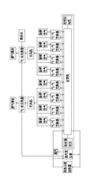

Image

  • Waste gas treatment and waste heat recovery device and method thereof
  • Waste gas treatment and waste heat recovery device and method thereof
  • Waste gas treatment and waste heat recovery device and method thereof

Examples


Embodiment Construction

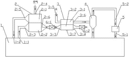
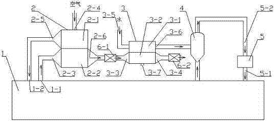
[0027] Such as figure 1 The exhaust gas treatment and waste heat recovery device shown includes: a setting machine 1 , a heat transfer medium heater 5 , a steam generator 4 and an air-air exchanger 2 .

[0028] The sizing machine 1 has an exhaust gas outlet 1-1 and a fresh air inlet 1-2.

[0029] The air-air exchanger has a new air chamber 2-1 and a waste air chamber 2-2 which are independent of each other; the new air chamber 2-1 has an air inlet 2-4 and an air outlet 2-5, and the air outlet 2 -5 is connected with the fresh air inlet 1-2 of the sizing machine 1; The exhaust gas outlet 1-1 is connected. The gas-gas exchanger 2 can adopt any kind of exchanger that can realize heat exchange between gases, preferably, such as figure 1 As shown, the air-gas exchanger 2 is divided into an upper fresh air chamber 2-1 and a lower exhaust gas chamber 2-2 by a tube sheet, the fresh air chamber 2-1 is a heat absorption section, and the exhaust gas chamber 2- 2 is the exothermic sect...


PUM


Abstract

The invention provides a waste gas treating and waste heat recycling device. The device comprises a setting machine, a thermal conductive medium heater, a steam generator and a gas-gas exchanger, and further comprises a gas-liquid exchanger, wherein the gas-liquid exchanger includes a liquid chamber and a gas chamber which are independent mutually; the gas chamber is provided with a gas inlet anda gas outlet; the gas inlet is connected with the waste gas outlet of the gas-gas exchanger by a draught fan, and the gas outlet is connected with the draught fan; the liquid chamber is provided witha water inlet and a water outlet; the water outlet is connected with the steam generator; the thermal conductive medium heater and the setting machine form a return circuit therebetween by an outlet medium pipe and a return medium pipe; and the steam generator is arranged on the return circuit. In addition, the invention further provides a waste gas treating and waste heat recycling method. The waste gas treating and waste heat recycling device disclosed by the invention is simple in structure and simple in operation, makes full use of heat energy of waste gases, reduces production cost, and is energy-saving and environmentally-friendly.

Description

technical field [0001] The invention relates to a waste heat recovery device, in particular to a waste gas treatment and waste heat recovery utilization device and method of a textile heat setting machine. Background technique [0002] The heat setting machine is a device that uses hot air to dry, arrange and shape the textile. There are many ways to supply hot air. Now, the air in the oven of the setting machine is mainly heated by a circulating heat conduction oil furnace. Different textiles require different temperatures in the oven, and the temperature of the exhaust gas is also different. Generally, the temperature required for shaping chemical fiber textiles is 200°C, and the temperature of the exhaust gas is 170°C; the temperature required for cotton fabrics is 140°C, and the temperature of the exhaust gas is 100°C. It can be seen that the discharge of exhaust gas is accompanied by a large amount of heat energy. According to calculations, each setting machine consum...

Claims


Application Information

Patent Timeline
IPC IPC(8): D06C7/02F28D7/00
Inventor 何丽娅
Owner 桐乡市好阳光能源科技有限公司
Learn More