Hybrid Excitation Shaft Radial Magnetic Suspension Bearing
A magnetic levitation bearing and mixed excitation technology, applied in the direction of shafts and bearings, bearings, mechanical equipment, etc., can solve the problems of coil heating, bearing electric power, etc., to reduce loss and temperature rise, low loss and temperature rise, and reduce ampere-turns number effect
- Summary
- Abstract
- Description
- Claims
- Application Information
AI Technical Summary
Problems solved by technology
Method used
Image

Examples
specific Embodiment approach 1
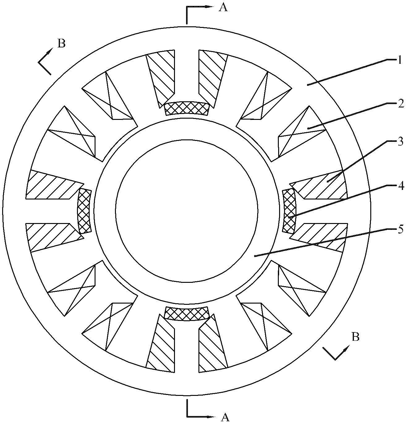
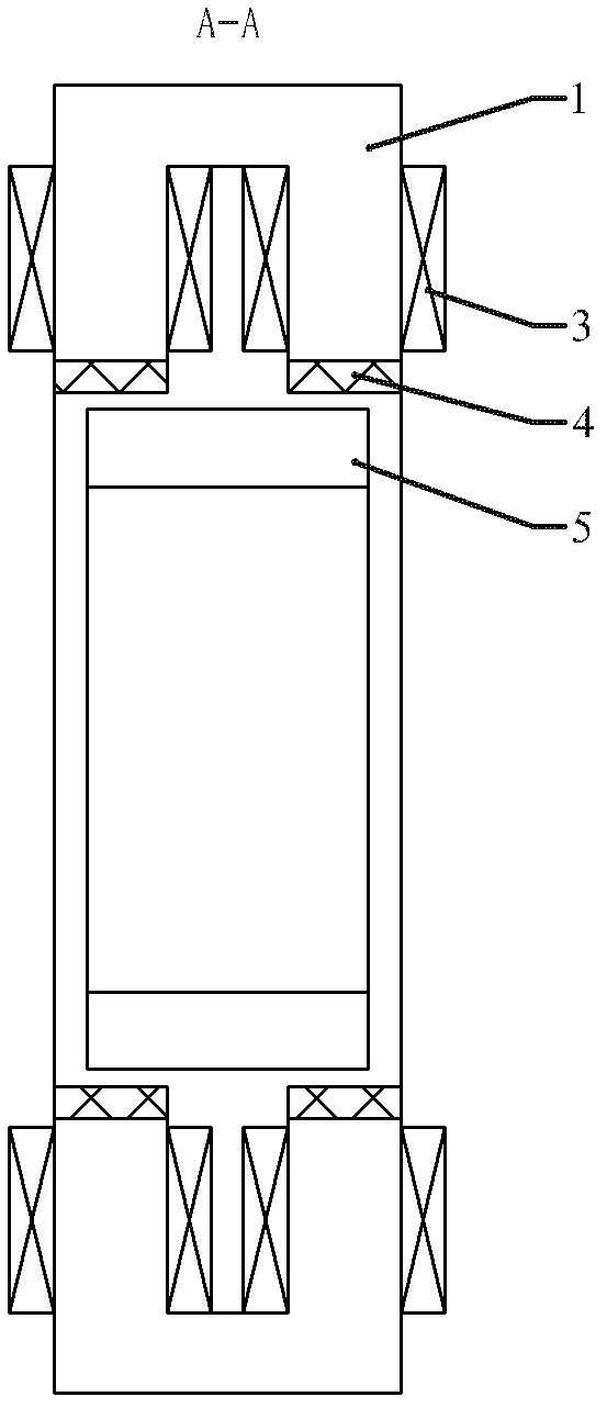
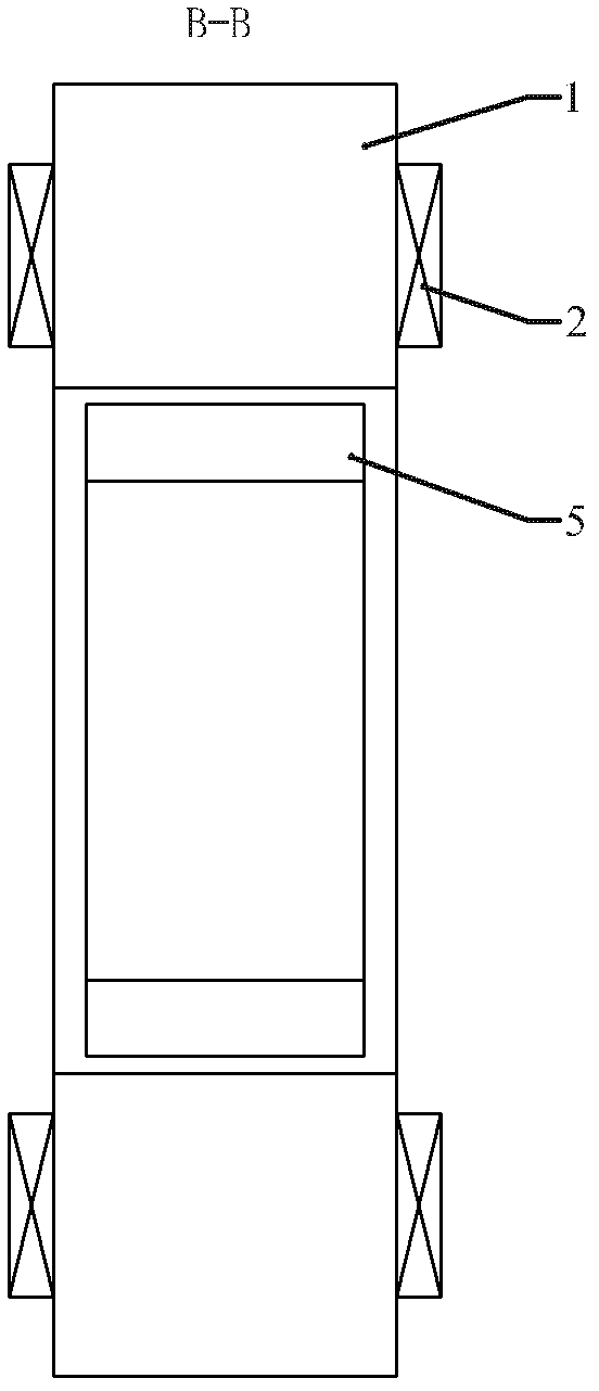
[0013] DETAILED DESCRIPTION OF THE PREFERRED EMBODIMENTS 1. The hybrid excitation shaft radial magnetic suspension bearing described in this embodiment includes a stator, a rotor, and an air gap; the stator includes a stator core 1, a radial force control winding 2, an axial force control winding 3, and stator permanent magnets 4. The stator core 1 is cylindrical, and 4n slots are opened in the axial direction on the inner surface of the cylindrical stator core 1, and 4n teeth are formed on the inner side of the stator core 1, where n is a natural number greater than 1, and along the circumference The 1st, 3rd, ..., (4n-1) teeth are axial winding teeth, the 2nd, 4th, ..., 4n teeth are radial winding teeth, and the axial winding teeth are double-toothed structures, see figure 2 As shown, the double-tooth structure is obtained by slotting along the circumferential direction at the axial middle position of the inner end surface of the axial winding tooth, and an axial force cont...
specific Embodiment approach 2
[0016] Specific Embodiment 2. The hybrid excitation shaft radial magnetic suspension bearing described in this embodiment includes a stator, a rotor and an air gap; the stator includes a stator core 1, a radial force control winding 2, an axial force control winding 3 and a stator permanent magnet 4; The stator core 1 is cylindrical, and 4n slots are opened in the axial direction on the inner surface of the cylindrical stator core 1, and 4n teeth are formed on the inner side of the stator core 1, where n is a natural number greater than 1, and the th 1, 3, ..., 4n-1 teeth are radial force winding teeth, and the 2nd, 4th, ..., 4n teeth are axial force winding teeth; each radial force winding tooth is wound with a diameter A direction force control coil, and a tile-shaped stator permanent magnet 4 is pasted and fixed on the inner end surface of each radial force winding tooth, and the stator permanent magnet 4 is radially magnetized or radially parallel magnetized , the magnetiz...
specific Embodiment approach 3
[0018] Specific Embodiment 3. The hybrid excitation shaft radial magnetic suspension bearing described in this embodiment includes a stator, a rotor and an air gap; the stator includes a stator core 1, a radial force control winding 2, an axial force control winding 3 and a stator permanent magnet 4; The stator core 1 is cylindrical, and the inner surface of the cylindrical stator core 1 is provided with 4n slots in the axial direction, and 4n teeth are formed on the inner side of the stator core 1, wherein n is a natural number greater than 1, and the stator core 1 The yoke between every two adjacent teeth is slotted in the axial direction, and a flat-shaped stator permanent magnet 4 is embedded in the groove, and the flat-shaped stator permanent magnet 4 is magnetized tangentially along the circumference , and the magnetization direction of each adjacent two flat-plate stator permanent magnets 4 is opposite; the 1st, 3rd, ..., 4n-1 teeth are radial force control coil teeth, a...
PUM
 Abstract
Description
Claims
Application Information
 - R&D
- Intellectual Property
- Life Sciences
- Materials
- Tech Scout
- Unparalleled Data Quality
- Higher Quality Content
- 60% Fewer Hallucinations
Browse by: Latest US Patents, China's latest patents, Technical Efficacy Thesaurus, Application Domain, Technology Topic, Popular Technical Reports.
© 2025 PatSnap. All rights reserved.Legal|Privacy policy|Modern Slavery Act Transparency Statement|Sitemap|About US| Contact US: help@patsnap.com