A fresh air unit

A technology of fresh air unit and fresh air channel, which is applied in the direction of ventilation system, space heating and ventilation, space heating and ventilation details, etc. It can solve the problems of energy consumption, wider adjustment range, and small compressor compression, etc., to save energy and cost, precise temperature and humidity control, and stable working conditions

Inactive Publication Date: 2011-12-07
TSINGHUA UNIV +1
View PDF6 Cites 33 Cited by
  • Summary
  • Abstract
  • Description
  • Claims
  • Application Information

AI Technical Summary

Problems solved by technology

[0005] 1. When the indoor and outdoor temperature difference is large, due to the limitation of the design heat exchange area of ​​the heat pump device, it is impossible to recover the heat of the exhaust air more efficiently;
[0006] 2. When the indoor and outdoor temperature difference is large, it is still necessary to start the compressor for heat recovery, which consumes a certain amount of energy;
[0007] 3. Due to technological requirements, the fresh air volume is generally constant and cannot be used as a means of regulating the heat pump unit. However, the outdoor fresh air temperature fluctuates greatly in winter, and the operating adjustment range of the heat pump device becomes wider, which is not conducive to the stable operation of the heat pump device. Especially, when the outdoor temperature When it is too low, the condensing temperature of the heat pump device is low, the compression ratio of the compressor is small, the heat pump works unstable, and the performance is poor

Method used


Image

  • A fresh air unit
  • A fresh air unit
  • A fresh air unit

Examples


Embodiment 1

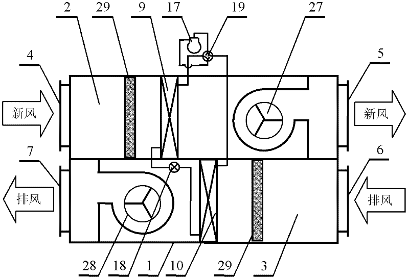
[0030] figure 2It is a structural schematic diagram of the first embodiment of a fresh air unit provided by the present invention, including a chassis 1 and a first heat pump device 14, wherein the chassis 1 is composed of mutually independent fresh air channels 2 and exhaust air channels 3, and the fresh air channels 2 It includes a fresh air inlet 4 and a fresh air outlet 5, and the exhaust air channel 3 includes an exhaust air inlet 6 and an exhaust air outlet 7; the first heat pump device 14 is composed of a first compressor 17, a first four-way valve 19, a first heat pump first The heat exchanger 15, the first throttling device 18 and the first heat pump and the second heat exchanger 16 are sequentially connected through refrigerant pipelines; the first heat pump first heat exchanger 15 is placed in the fresh air passage 2, the first heat pump second The second heat exchanger 16 is placed in the exhaust air channel 3, and it is characterized in that: the fresh air unit a...

Embodiment 2

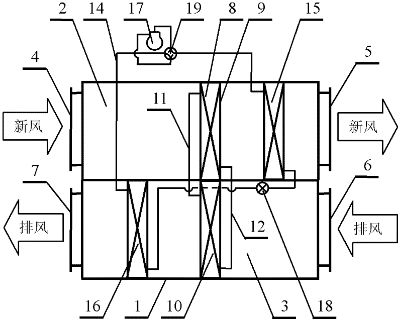
[0034] image 3 It is a structural diagram of the second embodiment of a fresh air unit provided by the present invention, including a chassis 1 and a first heat pump device 14, wherein the chassis 1 is composed of mutually independent fresh air channels 2 and exhaust air channels 3, and the fresh air channels 2 It includes a fresh air inlet 4 and a fresh air outlet 5, and the exhaust air channel 3 includes an exhaust air inlet 6 and an exhaust air outlet 7; the first heat pump device 14 is composed of a first compressor 17, a first four-way valve 19, a first heat pump first The heat exchanger 15, the first throttling device 18 and the first heat pump and the second heat exchanger 16 are sequentially connected through refrigerant pipelines; the first heat pump first heat exchanger 15 is placed in the fresh air passage 2, the first heat pump second The second heat exchanger 16 is placed in the exhaust passage 3; it is characterized in that: the fresh air unit also includes a he...

Embodiment 3

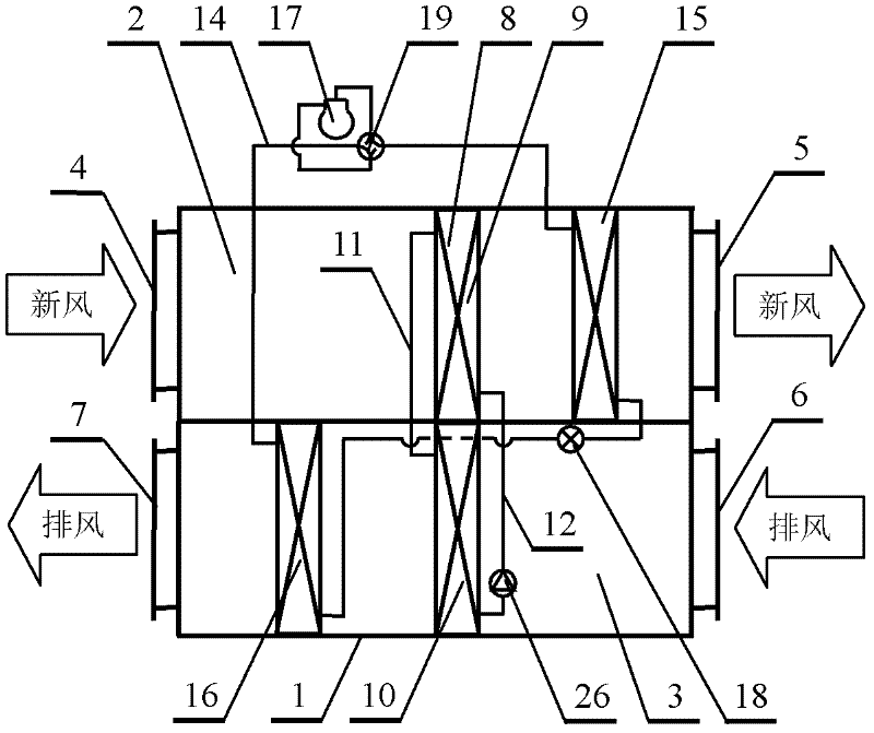
[0038] Figure 4 It is a structural principle diagram of the third embodiment of a fresh air unit provided by the present invention, including a chassis 1 and a first heat pump device 14, wherein the chassis 1 is composed of mutually independent fresh air channels 2 and exhaust air channels 3, and the fresh air channels 2 It includes a fresh air inlet 4 and a fresh air outlet 5, and the exhaust air channel 3 includes an exhaust air inlet 6 and an exhaust air outlet 7; the first heat pump device 14 is composed of a first compressor 17, a first four-way valve 19, a first heat pump first The heat exchanger 15, the first throttling device 18 and the first heat pump and the second heat exchanger 16 are sequentially connected through refrigerant pipelines; the first heat pump first heat exchanger 15 is placed in the fresh air passage 2, the first heat pump second The second heat exchanger 16 is placed in the exhaust air channel 3, and it is characterized in that: the fresh air unit ...


PUM


Abstract

A fresh air unit, including a chassis and a heat pump device, wherein the chassis is composed of mutually independent fresh air passages and exhaust air passages, the fresh air passage includes a fresh air inlet and a fresh air outlet, and the exhaust air passage includes an exhaust air inlet and an exhaust air outlet; A heat pump device is composed of a first compressor, a first four-way valve, a first heat pump first heat exchanger, a first throttling device, and a first heat pump second heat exchanger sequentially connected through a refrigerant pipeline; the fresh air unit It also includes a heat recovery device. The heat recovery device is a separate gravity heat pipe, a separate liquid pump circulation heat recovery device, an integral heat pipe, etc. The first heat exchanger of the heat recovery device is located at the fresh air inlet of the fresh air channel and the first heat pump first. Between the heat exchangers, the second heat exchanger of the heat recovery device is located between the exhaust inlet of the exhaust channel and the second heat exchanger of the first heat pump. The invention has the characteristics of efficient recovery of exhaust air heat, stable operating conditions, precise control of fresh air outlet parameters, energy saving and the like.

Description

technical field [0001] The invention relates to a fresh air unit, in particular to a device for recovering the heat of exhaust air to cool down or heat the fresh air, which belongs to the field of refrigeration and air-conditioning equipment, and is especially suitable for the occasion where a direct-flow all-air air-conditioning system is used. Background technique [0002] With the rapid development of society, many industrial production and process environments have a huge demand for fresh air and strict requirements on the constant temperature and humidity of the environment, resulting in a soaring energy consumption of the air conditioning system, which has become an important factor hindering industrial production. Reducing the energy consumption of the air conditioning system has significant economic and social benefits. [0003] The traditional fresh air treatment process is to send outdoor fresh air directly into the constant temperature and humidity air conditionin...

Claims


Application Information

Patent Timeline
Patent Type & Authority Applications(China)
IPC IPC(8): F24F12/00F24F13/02F24F13/30
CPCY02B30/563Y02B30/56
Inventor 李先庭熊双王宝龙徐明汪求学江岸石文星
Owner TSINGHUA UNIV
Why Eureka
Try Eureka