
A kind of optical demodulation method and its optical demodulation instrument based on otdr technology

A technology of an optical demodulator and a demodulation method, which is applied in the directions of light demodulation, optics, instruments, etc., can solve the problem that the number of sensor heads is difficult to achieve more.

Inactive Publication Date: 2011-12-07
武汉朗睿科技有限公司
View PDF4 Cites 15 Cited by
  • Summary
  • Abstract
  • Description
  • Claims
  • Application Information

AI Technical Summary

Problems solved by technology

[0006] However, due to the limitations of light source power, spectral width and measurement time, the maximum number of sensor heads for the above two solutions is difficult to achieve more

Method used


Image

  • A kind of optical demodulation method and its optical demodulation instrument based on otdr technology
  • A kind of optical demodulation method and its optical demodulation instrument based on otdr technology
  • A kind of optical demodulation method and its optical demodulation instrument based on otdr technology

Examples


Embodiment Construction

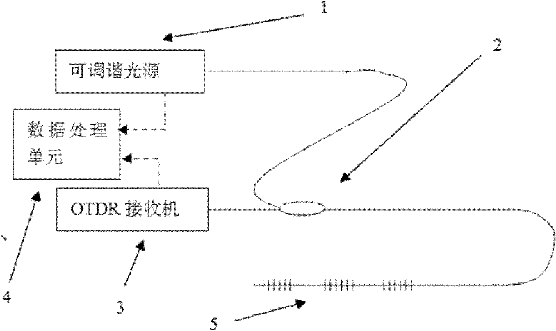
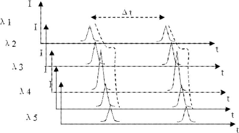
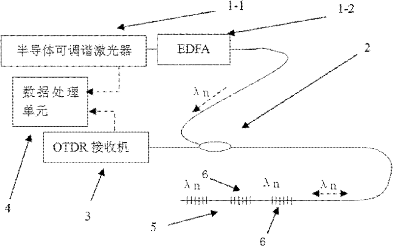
[0022] First, the implementation idea of ​​the present invention is generally described: a plurality of fiber gratings with weak reflections are connected in series on the optical fiber under test at an interval of 2m to 50m, and the reflectivity of each fiber grating is between 0.2% and 20%, forming a fiber grating array. The fiber grating is an ordinary fiber grating, an apodized fiber grating, a long period fiber grating or a weak grating. Then use a tunable light source, set a wavelength output, modulate the laser or use an external modulator to generate a 10ns to 100ns optical pulse. When the light pulse encounters the fiber grating and is reflected back to the detector, the fiber gratings at different positions return at different times, and a set of reflectivity and position data is obtained. Then, changing a wavelength output can be reflected at the same position, but the reflectivity is different, and another set of reflectivity and position data can be obtained. Com...


PUM


Abstract

The present invention relates to the demodulation technology of the fiber grating system, specifically to an optical demodulation method and an optical demodulation instrument based on OTDR technology. The circulator outputs short pulses to the measured optical fiber with multiple fiber gratings in series, and the optical signal reflected by the fiber grating enters the OTDR receiver through the coupler or circulator, and the output signal of the OTDR receiver is sent to the data processing unit; then it can be Tune the light source and set other wavelengths, repeat the above test, and send the data to the data processing unit. The data processing unit integrates the reflection intensity signals of different wavelengths of the fiber grating at the same position to obtain the reflection spectrum of the fiber grating; repeat the above process for the fiber gratings at different positions to obtain the reflection spectra of all fiber gratings connected in series on the optical fiber and / or optical fiber The distribution position of the grating on the optical fiber under test. The invention can break the limitation of the number of sensing heads on the optical fiber to be tested.

Description

technical field [0001] The invention relates to a demodulation technology of an optical fiber grating system, which can be used in petroleum and petrochemical, highway, bridge, electric power and other industries for temperature measurement, fire alarm, stress and strain monitoring and the like. Specifically, it relates to an optical demodulation method and an optical demodulator based on OTDR technology. The OTDR technology is used to identify the same or similar gratings, thereby increasing the number of probes of the grating demodulator. Background technique [0002] Fiber Bragg grating sensing technology is widely used in petroleum and petrochemical, highway, bridge, electric power and other industries, and can be used for temperature detection, fire alarm, stress and strain monitoring, etc. Because of the use of optical fiber-based sensing heads, which have the advantages of good insulation, no charge, long detection distance, and good reliability, they are gradually re...

Claims


Application Information

Patent Timeline
IPC IPC(8): G02F2/00H04B10/08H04B10/66
Inventor 李传文万琼
Owner 武汉朗睿科技有限公司
Learn More