A kind of led vacuum encapsulation device and vacuum encapsulation method

A technology of vacuum packaging and vacuum pumping device, which is applied in the direction of electrical components, circuits, semiconductor devices, etc., can solve the problems of unqualified packaged products, reduce LED light efficiency, affect LED light output, etc., and achieve the effect of improving the yield

Inactive Publication Date: 2011-12-07
东莞市福地电子材料有限公司
View PDF6 Cites 13 Cited by
  • Summary
  • Abstract
  • Description
  • Claims
  • Application Information

AI Technical Summary

Problems solved by technology

[0004] The problem existing in the above-mentioned prior art is that there is air in the cavity of the combination of the mold and the substrate, that is, the molding cavity of the encapsulated lens. If there are bubbles in the lens, the light will be refracted, the light distribution curve of the lens will be deformed, and the light output effect of the LED will be affected, thereby reducing the light efficiency of the LED.

Method used


Image

  • A kind of led vacuum encapsulation device and vacuum encapsulation method
  • A kind of led vacuum encapsulation device and vacuum encapsulation method

Examples


Embodiment 1

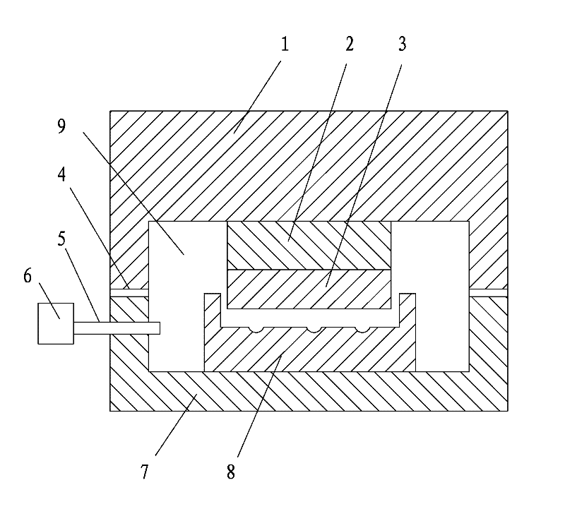
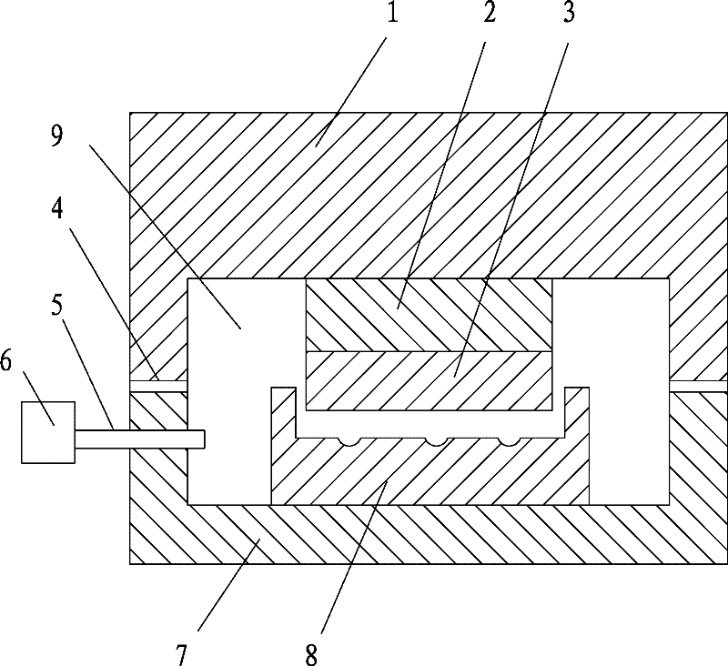
[0033] A kind of LED vacuum packaging device, such as figure 1 As shown, it includes a substrate 3 and a molding die 8, the substrate 3 is arranged above the molding die 8, the substrate 3 matches the molding die 8, and the vacuum packaging device is also provided with an upper mold 1 and a lower mold 7. The upper mold 1 and the lower mold 7 are matched with each other to form a sealed mold cavity 9, the base plate 3 and the forming mold 8 are arranged in the mold cavity 9, and the mold cavity 9 communicates with a vacuum pumping device. The upper mold 1 and the lower film 7 are buckled together, and the sealing gasket 4 is used to assist the sealing between the upper mold 1 and the lower film 7, which can ensure that the mold cavity 9 is in a vacuum environment after air extraction.

[0034] The air in the mold cavity 9 is drawn out by a vacuum pumping device. During the pressing process of the substrate 3 and the forming mold 8, the mold cavity 9 is in a vacuum environment, ...

Embodiment 2

[0042] A LED vacuum packaging method, comprising the following steps:

[0043] Step 1, inject glue, use glue injection equipment to pre-inject into the molding die 8 according to the required amount of glue injection;

[0044] Step 2, close the mold, close the upper mold 1 and the lower mold 7, the vacuum machine 6 works, vacuumize the mold cavity 9 through the vacuum tube 5, and drive the motor 2 to press the substrate 3 at the same time, and suppress the injected encapsulation glue;

[0045] Step 3, the substrate 3 extrudes the encapsulation glue, and the encapsulation glue flows into the die hole of the molding die 8;

[0046] Step 4. When the encapsulation glue changes from liquid to solid state, open the upper mold 1, lift up the substrate 3, and the encapsulation glue sticks to the surface of the substrate 3, and the LED encapsulation molding is completed.

[0047] Compared with the prior art, the present invention proposes LED packaging in a vacuum environment, and the...


PUM


Abstract

The invention relates to an LED (Light-Emitting Diode) encapsulating technology. An LED vacuum encapsulating device comprises a substrate and a forming die, wherein the substrate is arranged above the forming die, the substrate is matched with the forming die; and the vacuum encapsulating device is also provided with an upper die and a lower die which are mutually matched to form a sealed die cavity, the substrate and the forming die are arranged in the die cavity, and the die cavity is communicated with a vacuum air extractor. The LED vacuum encapsulating method comprises the following stepsof: injecting glue, namely injecting the required encapsulating glue into the forming die; closing the dies comprising the upper die and the lower die, vacuumizing the die cavity by virtue of a vacuum tube, and pressing the injected encapsulating glue by the substrate; extruding the encapsulating glue by the substrate, thus the encapsulating glue flows into a die hole of the forming die; and after the encapsulating glue is hardened, opening the upper die, thus LED encapsulating and forming are completed. In a pressing process of the substrate and the forming die, the die cavity is in a vacuumenvironment, the substrate presses silica gel without generating bubbles, thus the LED vacuum encapsulating device has high yield and good encapsulating effect.

Description

technical field [0001] The invention relates to LED packaging technology, in particular to an LED vacuum packaging device and a vacuum packaging method. Background technique [0002] The basic components of a current light-emitting diode (LED) include a substrate, an LED chip, a lens formed of encapsulant, and an inner lead. The inner lead connects the motor on the LED chip to the electrode on the substrate to ensure that the external electrode on the substrate transmits current to the LED chip; LED chip is a semiconductor material, and because it can emit visible light, it is generally used in signal indication, display lighting and other fields. The main function of the encapsulating colloid is to protect the LED chip and export the light emitted by the LED chip to act as an optical lens. Therefore, it is generally a transparent material, such as epoxy resin, silicone rubber, etc. [0003] In the prior art, the Chinese invention patent with the patent number "ZL2007100316...

Claims


Application Information

Patent Timeline
Patent Type & Authority Applications(China)
IPC IPC(8): H01L33/00H01L33/52
Inventor 陈小东
Owner 东莞市福地电子材料有限公司
Why Eureka
Try Eureka