Repair method of gas turbine moving blade and gas turbine moving blade

A technology for gas turbines and blades, which is applied to machines/engines, supporting elements of blades, mechanical equipment, etc., and can solve the problems of prone to crystallization cracks, poor weldability, and prone to defects in welded parts.

Inactive Publication Date: 2011-12-14
KK TOSHIBA
View PDF7 Cites 24 Cited by
  • Summary
  • Abstract
  • Description
  • Claims
  • Application Information

AI Technical Summary

Problems solved by technology

[0008] Gas turbine moving blades are formed of heat-resistant alloys such as Ni-based heat-resistant alloys, so they have excellent high-temperature strength, but poor weldability, and there is a problem that defects are prone to occur in welded part

Method used


Image

  • Repair method of gas turbine moving blade and gas turbine moving blade
  • Repair method of gas turbine moving blade and gas turbine moving blade
  • Repair method of gas turbine moving blade and gas turbine moving blade

Examples


Example

[0027] (First embodiment)

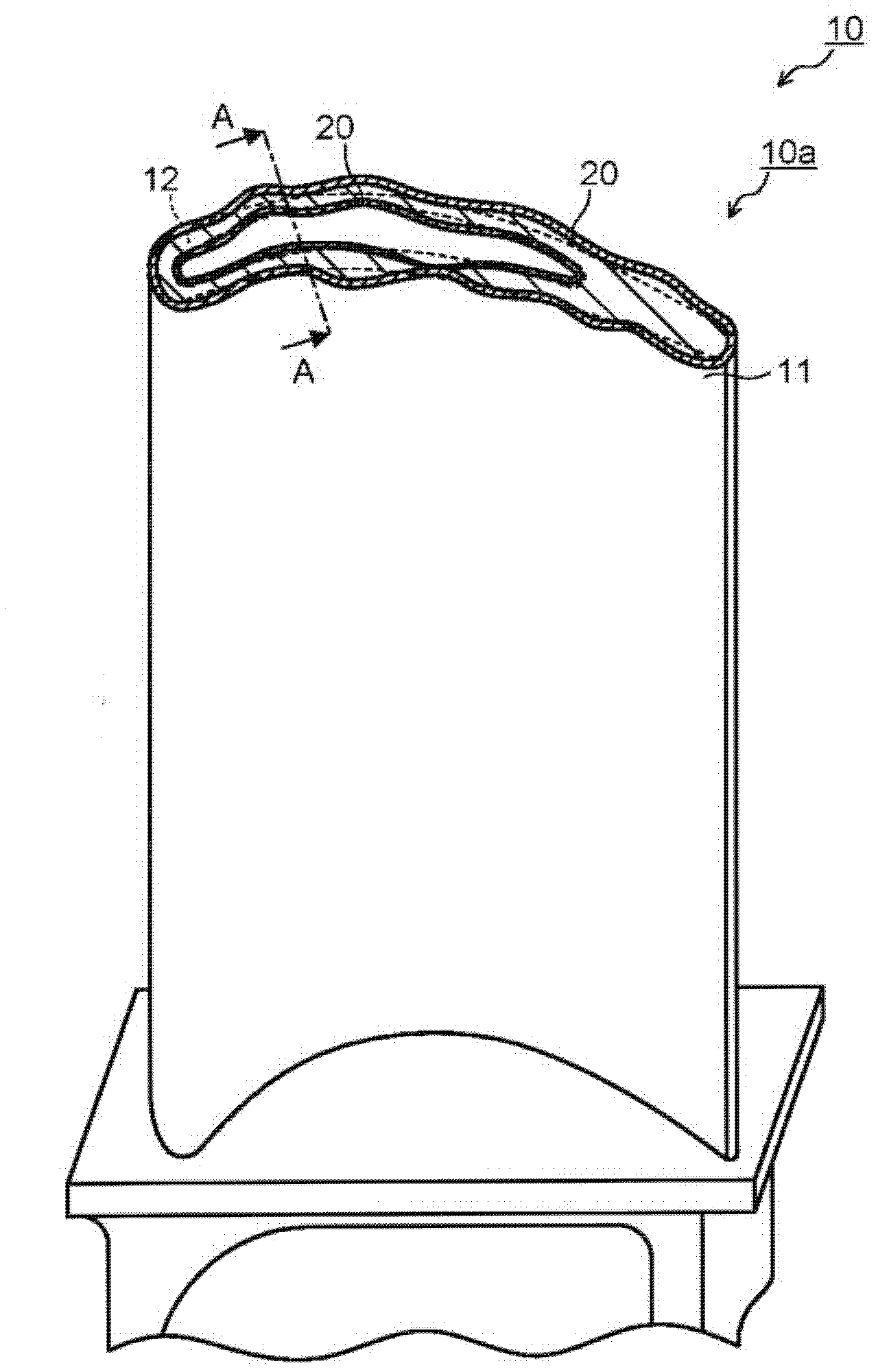
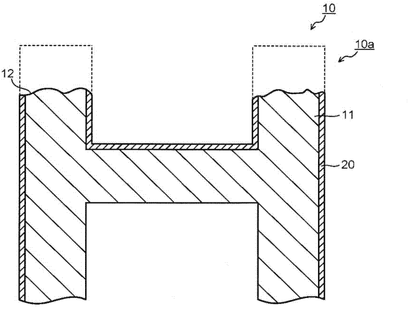
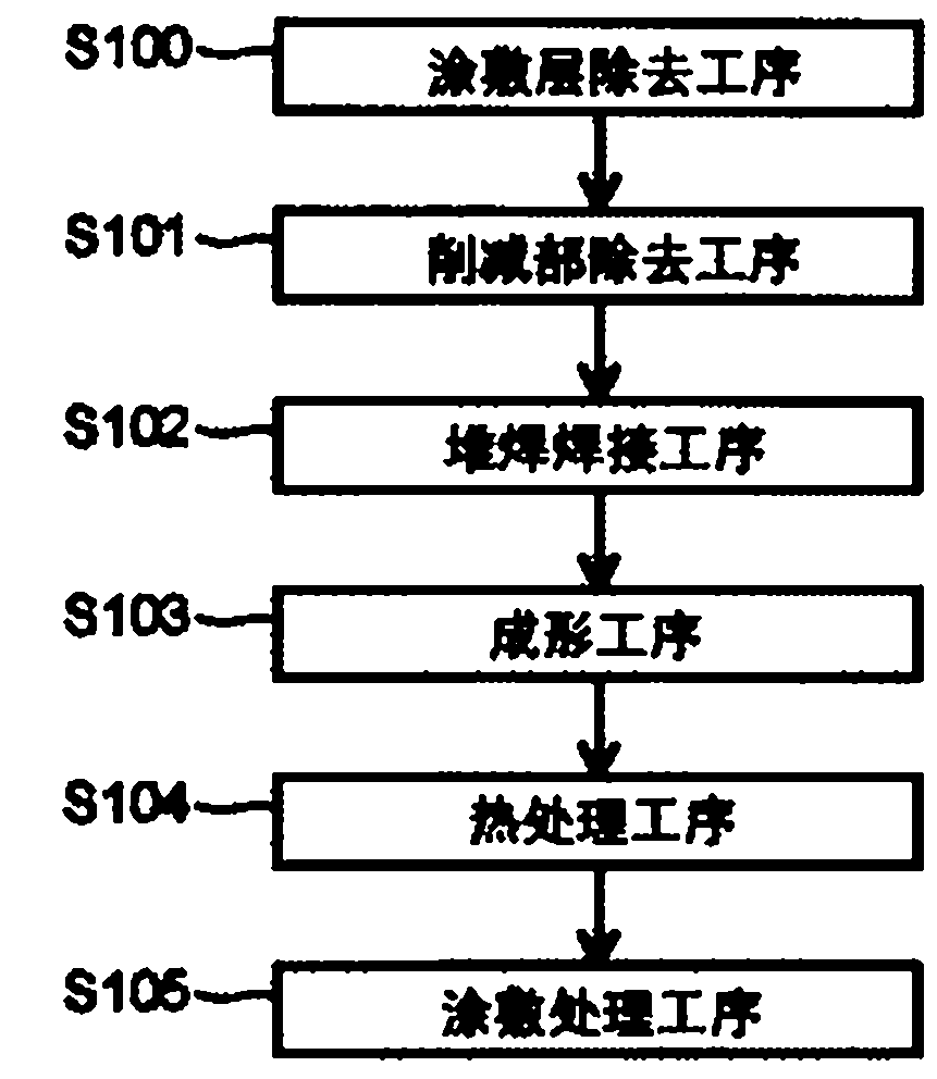
[0028] figure 1 It is a perspective view showing the gas turbine rotor blade 10 with the blade tip 10a cut. figure 2 Yes figure 1 The A-A cross section is a diagram showing the blade tip 10a of the gas turbine rotor blade 10. image 3 It is a figure which shows the process of the repair method of the gas turbine rotor blade of 1st Embodiment concerning this invention. Figure 4 ~ Figure 5 , Figure 7 ~ Figure 8 It is used to describe the process of the repairing method of the gas turbine rotor blade according to the first embodiment of the present invention. figure 1 Figure of the A-A section. Image 6 It is a diagram for explaining the laser welding method. Among them, in Figure 1 ~ Figure 2 , Figure 4 ~ Figure 5 In the dashed line, the cut part is shown.

[0029] In addition, in the description of the repairing method of the gas turbine motor blade according to the first embodiment of the present invention, as the gas turbine motor blade 10, an examp...

Example

[0057] (Second embodiment)

[0058] In the method for repairing gas turbine blades according to the second embodiment of the present invention, it is different from the method for repairing gas turbine blades according to the first embodiment in that the build-up welding process consists of a first build-up welding process and a second build-up welding process. The surfacing welding process constitutes, and the other repair methods are the same. Therefore, the surfacing welding process is mainly described here.

[0059] Picture 9 It is a figure which shows the process of the repair method of the gas turbine rotor blade of 2nd Embodiment concerning this invention. Here, the same reference numerals are given to the same steps as the steps of the method for repairing the gas turbine blades in the second embodiment, and redundant descriptions are omitted or simplified. Furthermore, as in the case of the gas turbine blade repair method of the first embodiment, when repairing the gas ...


PUM

PropertyMeasurementUnit
Thicknessaaaaaaaaaa
Diameteraaaaaaaaaa

Abstract

The present invention relates to a method of repairing a gas turbine moving blade capable of preventing defects such as cracks during overlay welding and performing highly reliable repairs when repairing a cut portion of a blade front end of a gas turbine moving blade, and the method for repairing Methods The gas turbine moving blades obtained after repairing. The repair method of the gas turbine rotor blade includes: removing the cut portion at the tip of the blade, and processing the tip of the blade into a flat cut portion removal process; using a laser to make the tip of the blade that is more ductile than the base material constituting the gas turbine rotor blade into a plane. The powder of the surfacing material is melted, and the surfacing is performed in multiple layers to form a surfacing welding process of a predetermined thickness; the shape of the surfacing part is processed into the same shape as the original blade tip before the reduction occurs The forming process; and the heat treatment process to remove the residual deformation caused by laser welding in the surfacing welding process.

Description

technical field [0001] Embodiments of the present invention relate to a method of repairing a moving blade of a gas turbine, and more particularly, to a method of repairing a moving blade of a gas turbine for repairing oxidation reduction (meat loss) occurring at the tip of the moving blade of a gas turbine, and The gas turbine moving blade obtained after repairing by this repairing method. Background technique [0002] The moving blades of the gas turbine are exposed to the high-temperature gas above 1000°C discharged from the combustor. Therefore, cooling is required for an effective design life cycle. Generally, the cooling of the gas turbine rotor blade is performed by supplying a part of the compressed air extracted from the compressor from the lower end of the implanted portion of the gas turbine rotor blade. The cooling air supplied to the inside of the gas turbine blade is released to the outside of the blade through a cooling passage formed in the blade-shaped por...

Claims


Application Information

Patent Timeline
IPC IPC(8): B23P6/00B23K26/34B23K35/28B23K31/00F01D5/28F01D25/00
CPCF01D5/005B23P6/007
Inventor 伊藤胜康日野武久酒井义明
Owner KK TOSHIBA
Why Eureka
Try Eureka