

A new device for improving the efficiency of wind turbines or wind power generators
A technology for wind turbines and fans, which is applied in the control of wind turbines, wind turbines, and wind turbines in the same direction as the wind, can solve problems such as low wind gathering efficiency, load impact, and no effect.
- Summary
- Abstract
- Description
- Claims
- Application Information
AI Technical Summary
Problems solved by technology
Method used
Image

Examples
Embodiment 1
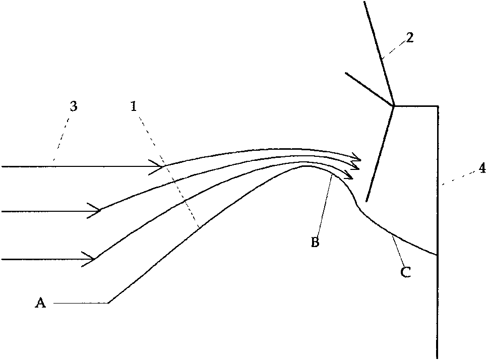
[0097] Such as figure 1 , figure 2 , image 3 , Figure 4 as shown, figure 1 It is a front view schematic diagram of a structural principle of the present invention, the wind gathering surface is the connection of two smooth curved surfaces, the section A-B is convex upward, the section B-C is concave upward, and the highest part of the wind gathering surface is higher than the bottom part of the wind sweeping surface of the blade , so that the wind gathered in section A-B can most effectively reach the most effective part of the fan blade; The bottommost part of the surface, if it is a downwind wind turbine, is placed horizontally behind and below the wind-sweeping surface of the wind wheel. The wind-gathering surface is defined in the present invention as a convex-concave surface. The advantage is that the wind gathering position and wind gathering direction are accurate and the effect is good.
[0098] figure 2 It is a schematic diagram of the left view of the struc...
Embodiment 2
[0100] Similarly, if Figure 5 , figure 2 , image 3 , Image 6 as shown,
[0101] Figure 5 It is a schematic diagram of the front view of the structural principle of the present invention. The wind gathering surface is a smooth convex surface or a half-barrel surface. At the rear and lower part of the wind-sweeping surface of the wheel, the highest part of the convex surface is higher than the bottommost part of the wind-sweeping surface of the blade. The wind-gathering surface is defined as a convex-convex surface in the present invention.
[0102] figure 2 It is a schematic diagram of the left view of the structural principle of the present invention, image 3 It is a top view schematic diagram of the structural principle of the present invention;
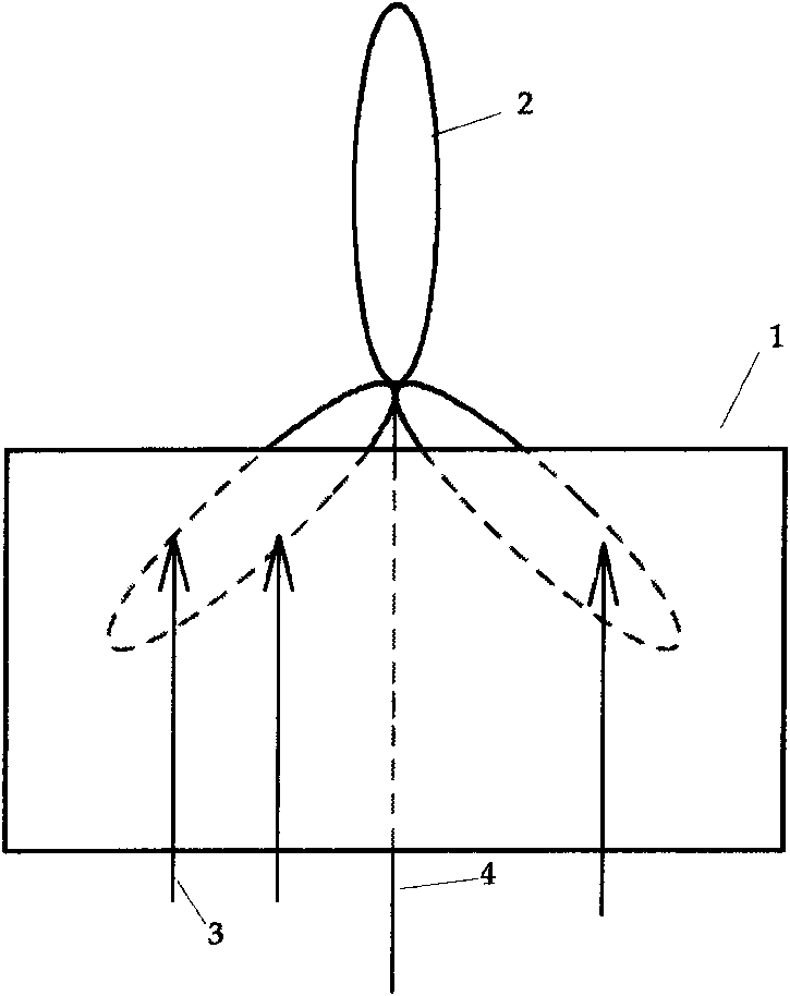
[0103] Image 6 It is an overall schematic diagram of a structure principle of the present invention.
Embodiment 3
[0105] Similarly, if Figure 7 , figure 2 , image 3 , Figure 8 as shown,
[0106] Figure 7 It is a schematic diagram of the front view of the structure principle of the present invention. The wind gathering surface is a streamlined curved surface. The D-E section is a slow rising section, and the E-F section is a steep descending section. machine, then horizontally placed on the back and lower side of the wind rotor sweeping surface, the highest position of the convex surface is higher than the bottom position of the blade sweeping surface, and the wind gathering surface is defined as: gentle and steep surface in the present invention. The advantage is that the wind gathering position is accurate.
[0107] figure 2 It is a schematic diagram of the left view of the structural principle of the present invention, image 3 It is a top view schematic diagram of the structure principle of the present invention, Figure 8 It is an overall schematic diagram of a structure...
PUM
 Abstract
Description
Claims
Application Information