A composite heat absorber of high temperature air and molten salt

A high-temperature air, heat sink technology, applied in indirect heat exchangers, heat exchanger types, solar collectors, etc. Stress problem, the effect of speeding up salt discharge and improving heat exchange efficiency

Inactive Publication Date: 2011-12-14
INST OF ELECTRICAL ENG CHINESE ACAD OF SCI
View PDF9 Cites 14 Cited by
  • Summary
  • Abstract
  • Description
  • Claims
  • Application Information

AI Technical Summary

Problems solved by technology

[0003] The purpose of the present invention is to overcome the problems of large thermal stress in the pipes of the molten salt heat absorber in the prior

Method used


Image

  • A composite heat absorber of high temperature air and molten salt
  • A composite heat absorber of high temperature air and molten salt
  • A composite heat absorber of high temperature air and molten salt

Examples


Embodiment 1

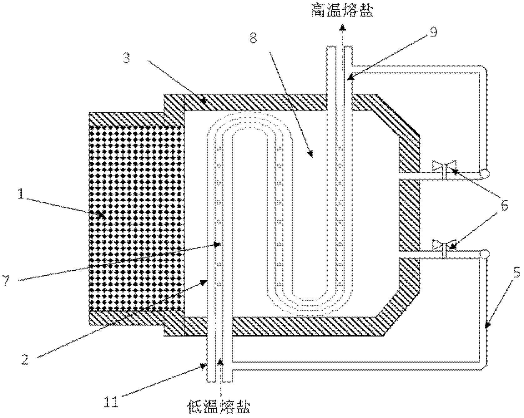
[0034] Embodiment 1: High-temperature air and molten salt composite heat absorber with heat pipe horizontal pipe structure.

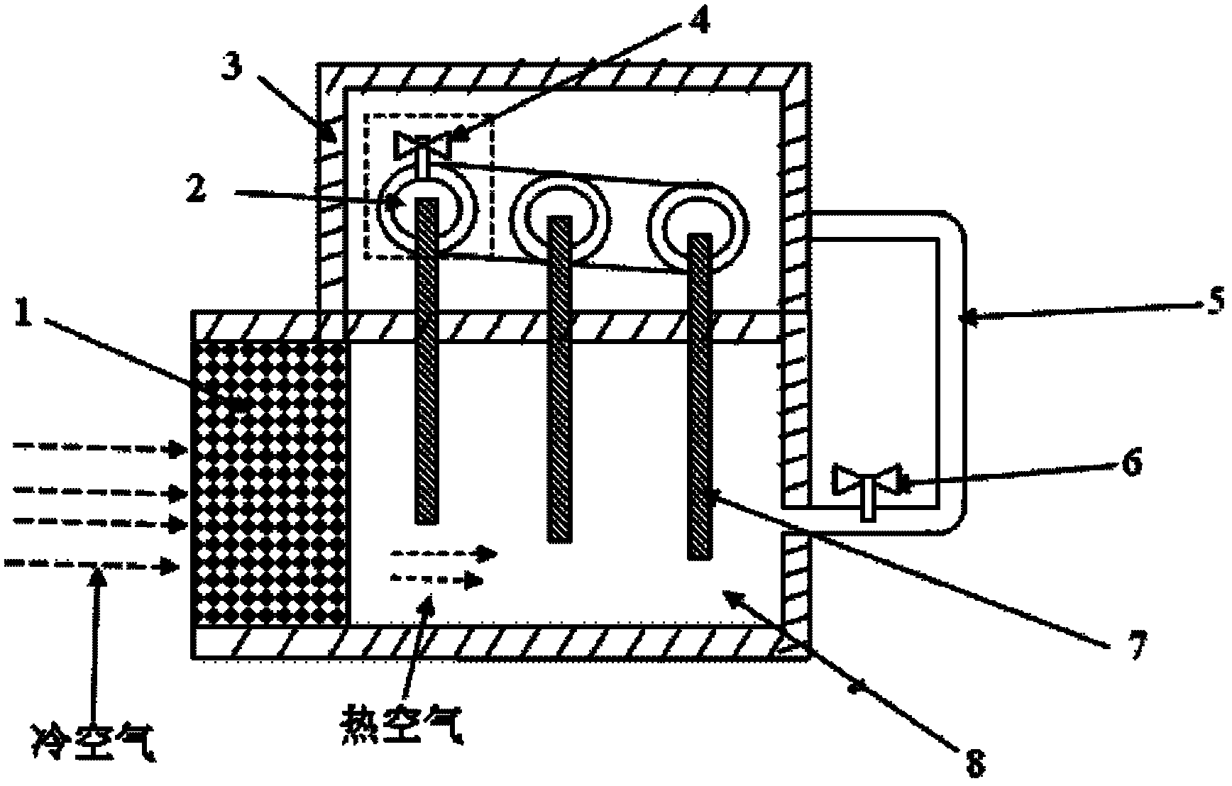
[0035] In the preheating condition, the control system makes some of the heliostats in the heliostat field 19 in the working state, and the solar energy is focused by some of the heliostats to form a light spot with a low energy flux density. At the same time, the induced draft fan 15 is started, and the cold air Drawn by the fan 15, it flows through the heat absorber 1 with a porous structure. The cold air passes through the heat exchange with the heat absorber 1 of porous structure, and finally enters the heat exchange chamber 8, opens the heat tracing valve 6, and makes it in an open state, and the hot air enters the fan pipe 5 through the heat tracing valve 6. At this time, there is no molten salt working medium flowing through the molten salt heat absorbing pipe 2 and the molten salt pipeline 11 . The thermocouple in the heat exchange chamber 8 ca...

Embodiment 2

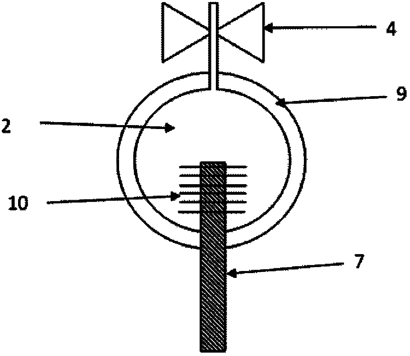
[0036] Example 2: High-temperature air and molten salt composite heat absorber with vertical structure without heat pipes

[0037] In the case of preheating, the control system makes part of the heliostats in the heliostat field 19 in the working state, the temperature of the porous structure heat absorber 1 absorbs solar energy rises, and at the same time the induced draft fan 15 is started, and the cold air passes through the porous structure heat absorber 1 1, finally enters the heat exchange chamber 8, and the air in the heat exchange chamber 8 has a relatively high temperature at this time. Then the heat tracing valve 6 is opened, and the air enters the fan duct 5 through the heat tracing valve 6 . Through feedback control, the temperature of the air in the heat exchange chamber 8 is kept stable at about 300°C. At the same time, the heat-tracing air enters the interlayer 9 of the inner and outer pipes of the molten salt heat-absorbing pipe 2 through the fan pipe 5, and t...


PUM


Abstract

The invention relates to a high-temperature air and molten salt composite heat absorber comprising a porous-structure heat absorber (1), a heat exchange cavity (8), a heat pipe (7) and a molten salt heat absorption pipe (2), wherein the porous-structure heat absorber (1) is arranged at a daylight opening of the high-temperature air and molten salt composite heat absorber (13); the molten salt heat absorption pipe (2) and the heat pipe (7) are respectively located in upper and lower cavities of the heat exchange cavity (8); one end of the heat pipe (7) is located in the lower cavity of the heat exchange cavity (8); the other end of the heat pipe (7) is inserted in an inner pipe of the molten salt heat absorption pipe (2); and the end of the heat pipe (7), located in the inner pipe of the molten salt heat absorption pipe (2), is provided with fins. In the invention, the molten salt heat absorption pipe (2) adopts a sleeve structure; molten salt circulates in the inner pipe and high-temperature air circulates in an interlayer (9) between inner and outer pipelines; the heat exchange cavity (8) and the interlayer (9) between inner and outer pipelines are communicated by utilizing a fanduct (5); and the make-break is controlled by a heat tracing valve (6).

Description

technical field [0001] The invention relates to a high-temperature heat absorber for a solar tower thermal power station, in particular to a high-temperature air and molten salt composite heat absorber. Background technique [0002] In the existing various tower-type solar thermal power generation test stations, the heliostat system and the power generation system are basically the same, and the only difference is the heat absorption and heat transfer system. Among various heat absorption and thermal energy transfer systems, the most commercial potential and the most researched are molten salt system, air system and saturated steam system. Using molten salt as the working medium of the heat absorber, the system can operate under normal pressure and improve safety; the heat transfer working medium has no phase change in the entire heat absorption and heat transfer cycle, and the heat capacity of molten salt is large, and the system is easy to achieve large capacity Heat stor...

Claims


Application Information

Patent Timeline
IPC IPC(8): F24J2/28F24J2/32F24J2/34F24S10/80F24S10/95
CPCY02E10/44F24S10/80F24S10/95F24S20/20F24S80/20F28D2020/0047
Inventor 张强强李鑫常春王志峰白凤武刘鸿
Owner INST OF ELECTRICAL ENG CHINESE ACAD OF SCI
Why Eureka
Try Eureka