Non-electric CO2 Refrigeration Dehumidification Air Conditioner

A carbon dioxide, refrigeration and dehumidification technology, applied in safety devices, mining equipment, earthwork drilling and mining, etc., can solve the problems of normal supply, large consumption, high battery capacity requirements, etc., and achieve good effect and low cost

Inactive Publication Date: 2011-12-21
阳泉煤业集团华越机械有限公司
View PDF6 Cites 5 Cited by
  • Summary
  • Abstract
  • Description
  • Claims
  • Application Information

AI Technical Summary

Problems solved by technology

The electric air conditioner is highly dependent on electricity. If the external power supply is cut off after a dangerous situation occurs, it must rely on the internal battery for power supply, which requires a higher capacity of the battery. At the same time, the compressor of the electric air conditioner is placed outside the cabin. Explosion-proof requirements are high, there are potential safety hazards, and when the outside temperature is higher than 50°C, the air conditioner cannot be cooled; the amount of ice storage cooling is relatively large, so it is necessary to have enough space in the rescue cabin or refuge chamber for storage Ice also has high requirements for ice insulation, and ice replacement is more frequent; ventilation and cooling is mainly to connect the compressed air pipeline in the rescue cabin or refuge chamber with the underground compressed air system, so as to provide protection for the personnel in the escape facility. Oxygen supply and cooling, but the power supply of the compressed air system cannot be guaranteed after a dangerous situation occurs, the compressed air pipeline is not damaged, and the compressed air does not contain toxic and harmful gases; liquid carbon dioxide vaporization and heat absorption is one of the most used methods at present. At present, the most used is a jet refrigeration air conditioner imported from Australia, and the price is relatively high.

Method used


Image

  • Non-electric CO2 Refrigeration Dehumidification Air Conditioner
  • Non-electric CO2 Refrigeration Dehumidification Air Conditioner
  • Non-electric CO2 Refrigeration Dehumidification Air Conditioner

Examples


Embodiment Construction

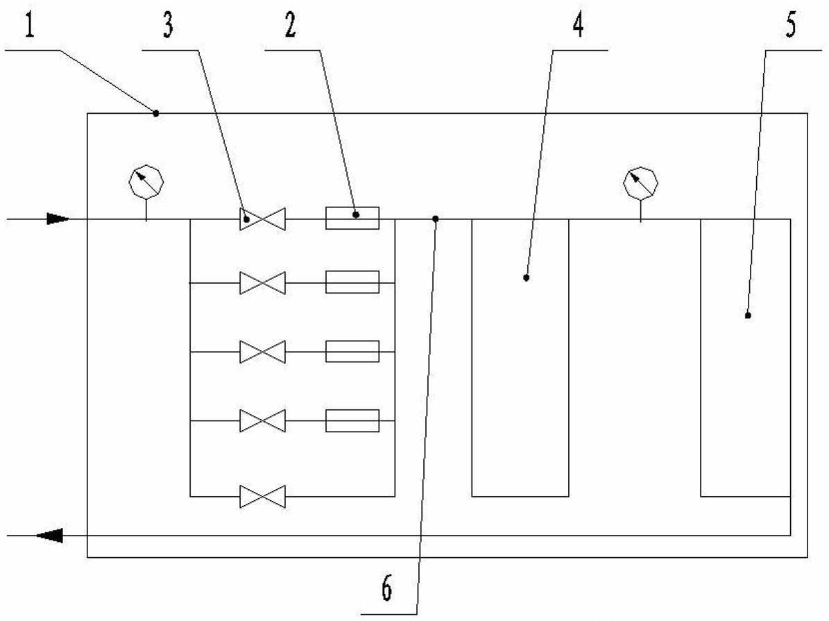
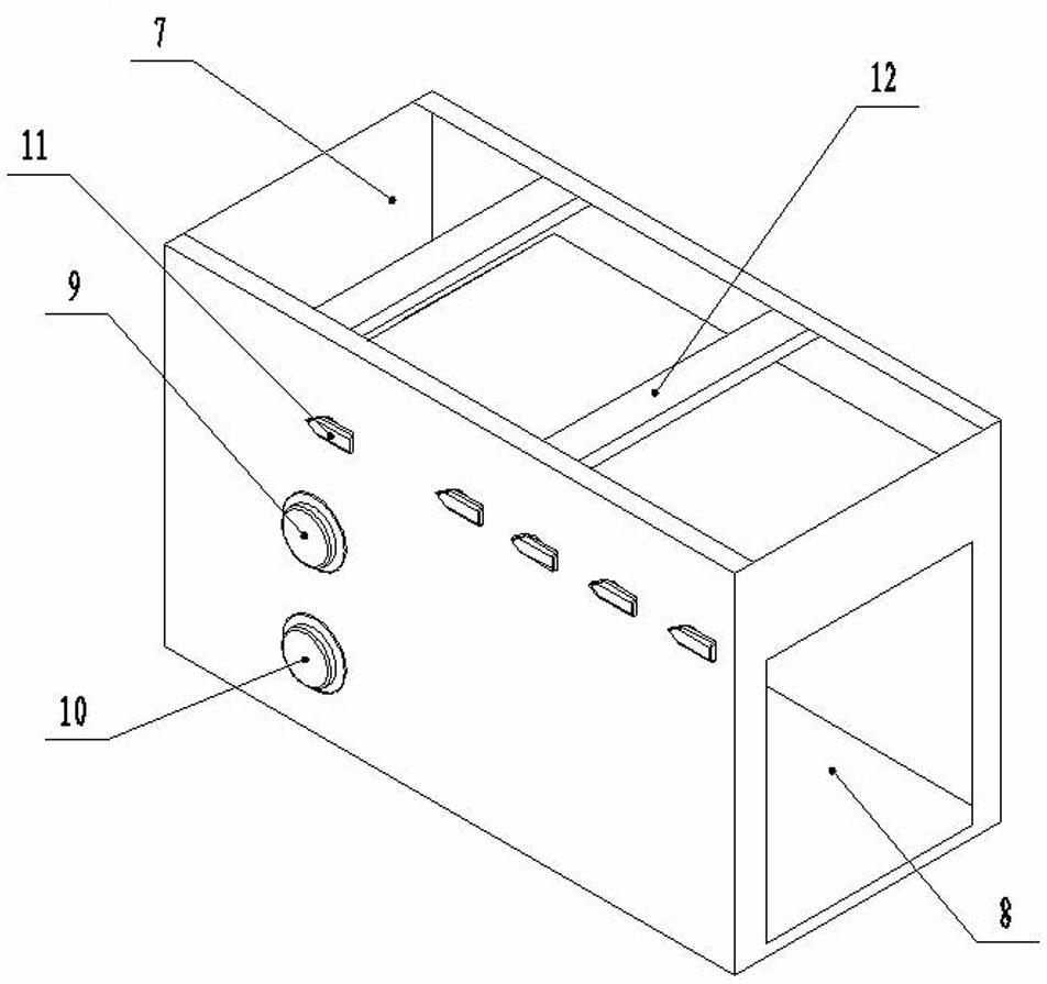
[0014] The box body 1 is assembled from panels processed from sheet metal. After the panels are processed, they are treated with corrosion resistance. The throttling pressure reducer 2 and the control valve 3 are installed on the inner side of the box body 1, the evaporator is installed at the air outlet 8, the pneumatic fan 5 is installed behind the evaporator, and the high-pressure pressure gauge 9 showing the inflow and outflow of carbon dioxide is installed on the side of the pneumatic fan 5 And low pressure gauge 10.

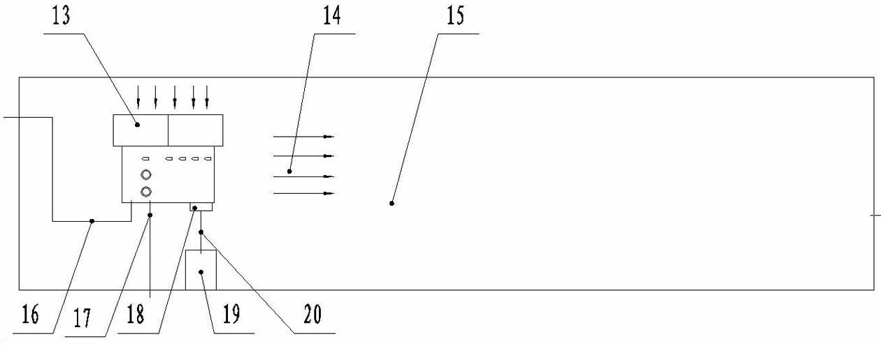
[0015] Liquid carbon dioxide enters the drier 22 from the liquid inlet thick pipe 16 and then filters out moisture therein, removes solid impurities therein through a fine mesh 23 , and then enters the elongated pipe 24 . When the liquid carbon dioxide passes through the slender tube, the pressure decreases and the flow rate increases. Due to the heat insulation of the thermal insulation material, the temperature of the liquid carbon dioxide decreases, and ...


PUM


Abstract

A non-electric carbon dioxide refrigeration dehumidification air conditioner, the purpose is to reduce the temperature and humidity inside the rescue cabin or chamber when the power is cut off; Fan, liquid inlet pipeline and exhaust pipeline, high-pressure pressure gauge and low-pressure pressure gauge, flared adapter; emergency control valve, control valve, high-pressure pressure gauge and low-pressure pressure gauge are installed on the front of the box; the right side of the box There is an air outlet on the surface, and an air inlet on the top; the throttling pressure reducer includes a thick liquid inlet pipe, a dryer, a fine mesh, a slender pipe, an outlet, an insulation material and a pressure reducer shell; the dryer is a cylindrical container A fine mesh for removing solid impurities in the refrigerant is installed near the slender tube inside, and a desiccant for absorbing water is installed at the front end of the fine mesh; the internal gap of the pressure reducer shell is filled with thermal insulation material, and the thermal insulation material is made of zirconium-containing ceramic fiber.

Description

technical field [0001] The invention relates to a non-electric carbon dioxide refrigeration and dehumidification air conditioner, which is mainly installed in a coal mine rescue cabin or refuge chamber. Background technique [0002] Controlling the temperature and humidity inside the rescue chamber or refuge chamber is one of the difficult problems hindering the progress of the current rescue chamber and refuge chamber. The rescue cabin or refuge chamber is a key component of the coal mine escape system. It is heat-insulated and airtight when it is processed or constructed. Therefore, when a mine disaster occurs underground and the underground personnel enter the rescue chamber or chamber, the power supply will be cut off. , the heat and sweat of the human body will increase its internal temperature and humidity. In order to make its internal living environment suitable for human survival, it is necessary to control its internal temperature and humidity to a range suitable f...

Claims


Application Information

Patent Timeline
Patent Type & Authority Applications(China)
IPC IPC(8): E21F3/00E21F11/00
Inventor 史慧锦康晋
Owner 阳泉煤业集团华越机械有限公司
Why Eureka
Try Eureka