Heavy Duty Overrunning Clutch

An overrunning clutch, heavy-duty technology, used in clutches, one-way clutches, mechanical equipment, etc., can solve the problems of reduced work efficiency, easy deflection of rollers, and fewer installations, reducing maintenance and use costs, guaranteeing Processing and assembly accuracy, the effect of increasing the bearing capacity

Active Publication Date: 2011-12-21
SOUTHWEST UNIVERSITY
View PDF4 Cites 22 Cited by
  • Summary
  • Abstract
  • Description
  • Claims
  • Application Information

AI Technical Summary

Problems solved by technology

The limit seat of the overrunning clutch is generally formed in one piece on the outer ring or the inner ring, and the processing process is relatively complicated, which not only reduces the work efficiency, but also makes the processing cost higher
Therefore, in order to facilitate processing and ensure processing accuracy, the inner star wheel type is widely used, but for the structure of the outer ring as an active transmission, it is not conducive to adapt to the transmission law of the overrunning clutch, resulting in shortened service life or affecting the transmission effect; at the same time, Due to the strong integrity, if the parts are damaged, the overrunning clutch will be scrapped as a whole, and the cost of use will be wasted.
[0004] As for the overrunning clutch of the outer planetary wheel, since the limit seat is processed on the inner circle of the outer star wheel, the engaging body (roller) is limited by the space

Method used


Image

  • Heavy Duty Overrunning Clutch
  • Heavy Duty Overrunning Clutch
  • Heavy Duty Overrunning Clutch

Examples


Example Embodiment

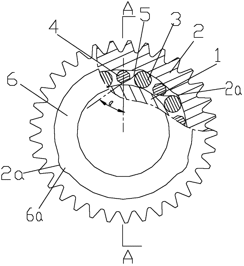
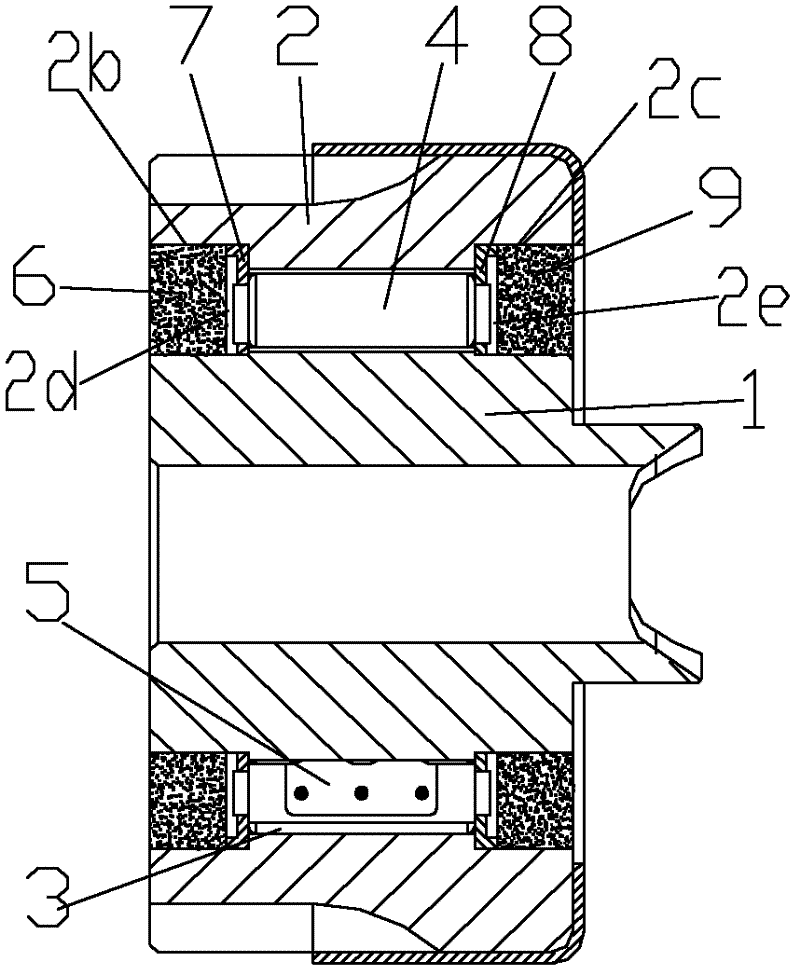
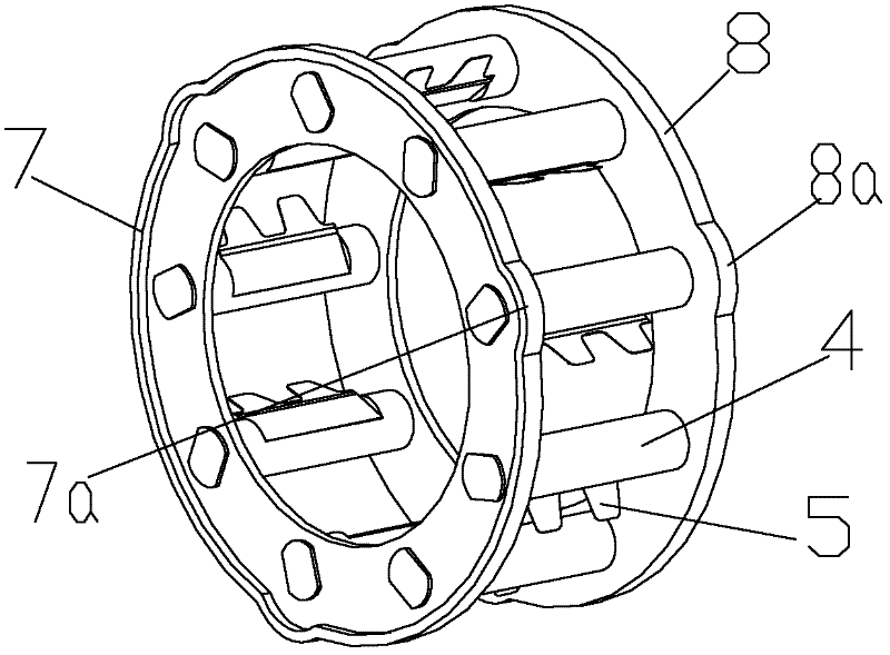
[0023] figure 1 It is a schematic diagram of the structure of the present invention, figure 2 for figure 1 Sectional view along A-A direction, image 3 It is a perspective view of the cage of the present invention, Figure 4 It is a schematic diagram of the cooperation relationship between the support column and the support ring II of the present invention, as shown in the figure: the heavy-duty overrunning clutch of this embodiment includes an outer ring 2, an inner ring 1 and a roller 3, and the inner ring 1 is not limited to the annular The structure can also be a shaft-like structure as shown in the figure; the inner circle of the outer ring 2 forms an engaging groove 2a for engaging or disengaging with the roller 3. This structure is similar to the prior art, and the engaging groove 2a can be generally used. The wedge-shaped structure or the arc structure; for the present invention, the arc structure is preferred; it also includes a cage, and the cage includes a suppo...


PUM


Abstract

The invention discloses a heavy-duty overrunning clutch, which comprises an outer ring, an inner ring, a plurality of rollers and a retaining frame. The retaining frame comprises a support ring I, a support ring II and a plurality of support columns corresponding to the rollers. Spring plates are fixedly arranged on the support columns along the axial direction and are used for applying pre-tightening force on the rollers along the engagement direction of an engagement slot. The direct processing of a limit seat on the outer ring can be avoided, the working efficiency can be increased, the processing cost can be reduced, the service life can be prolonged, and the transmission effect can be guaranteed. Moreover, relevant components can be replaced easily after being damaged, the outer ringneeds not to be rejected as a whole, and the cost of maintenance and use can be reduced. The axial length of the overrunning clutch and the rollers can be increased theoretically indefinitely, the engagement length can be increased, and thus the bearing capacity of the overrunning clutch can be improved. Meanwhile, the pre-tightening force can be applied at multiple points of the rollers according to needs, and the limiting balance for the rollers can be guaranteed while the axial length is ensured, so that the rollers cannot deviate from the axial line of the inner ring. Therefore, the stable operation of the overrunning clutch can be ensured, and mechanical failure can be avoided.

Description

technical field [0001] The invention relates to a clutch device for motor vehicles and mechanical transmission, in particular to an overrunning clutch. Background technique [0002] The overrunning clutch is a basic component that appears with the development of power products. It is an important component used for power transmission and separation between the prime mover and the working machine or between the driving shaft and the driven shaft inside the machine. It is mainly a device with a self-clutching function by utilizing the speed change of the main and driven parts or the transformation of the rotation direction. In practice, most of them are clutches that use the meshing of teeth, the meshing of ratchets and pawls, or the wedging action of rollers and wedges to transmit motion or torque in one direction. [0003] Roller overrunning clutch is widely used in higher speed occasions because of its uniform and stable transmission, large load capacity and easy manufactu...

Claims


Application Information

Patent Timeline
IPC IPC(8): F16D41/064
Inventor 薛荣生黄敦新
Owner SOUTHWEST UNIVERSITY
Why Eureka
Try Eureka