A new two-dimensional beam deflection method and device

A new type of beam deflection technology, applied in optics, nonlinear optics, instruments, etc., can solve problems such as unevenness and discrete beam deflection angle, and achieve the effect of uniform angle distribution, quasi-continuous angle distribution, and high precision.

Active Publication Date: 2011-12-21
NAT UNIV OF DEFENSE TECH
View PDF1 Cites 17 Cited by
  • Summary
  • Abstract
  • Description
  • Claims
  • Application Information

AI Technical Summary

Problems solved by technology

[0003] In order to solve the problem of discrete and non-uniform beam deflection angles in the prior art (such as image 3 As shown), the present invention provides a method and device for realizing quasi-continuous deflection control of light beams based on a single-chip liquid crystal spatial light modulator, and the method and device can realize angular deflection in a two-dimensional range, filling the current gap based on single-chip A gap in the field of two-dimensional beam deflection of liquid crystal spatial light modulator

Method used


Image

  • A new two-dimensional beam deflection method and device
  • A new two-dimensional beam deflection method and device
  • A new two-dimensional beam deflection method and device

Examples


Embodiment Construction

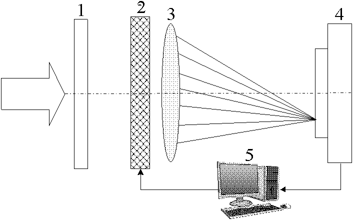
[0041] The beam deflection device includes a polarizer 1, a liquid crystal spatial light modulator 2, a lens 3, an image sensor 4, and a computer 5, wherein the polarizer 1 is positioned before the liquid crystal spatial light modulator 2 to generate polarization parallel to the long axis of the liquid crystal molecule The lens 3 is located behind the liquid crystal spatial light modulator 2 to obtain far-field light spots, and the image sensor 4 is located behind the lens 3 to collect light spot information. The computer and image sensor can collect and analyze the deflected light spot in real time. The whole system works like figure 1 shown.

[0042] Its specific working process is:

[0043] 1. Calibrate the beam deflection system so that the image sensor is located at the focal plane of the lens with the smallest spot.

[0044] 2. Record the position of the undeflected light spot, based on the image processing method, through the threshold method or filter processing, and...


PUM


Abstract

The invention provides a novel purely electric control two-dimensional light beam deflection method and device. The method and device can realize angular deflection in a two-dimensional range, and fills the blank in two-dimensional light beam deflection field of the existing space light modulator based on a single liquid crystal. According to the invention, the quasi-continuous deflection controlof the light beam can be conveniently realized in the two-dimensional range by adopting the space light modulator based on the single liquid crystal and using a novel driving principle; therefore, the light beam deflection is convenient for operation and high in precision and has the advantage of uniform and quasi-continuous angle distribution. Two parameters alpha'and beta'generating a phase image are both continuous and controllable parameters; therefore, the problem that light beam deflection angles are discrete and not distributed uniformly in the traditional method is solved. The invention provides a simple method for realizing the deflection of the two-dimension light beam, and fills the blank of the traditional method in the two-dimension light beam deflection field.

Description

technical field [0001] The invention relates to a novel purely electronically controlled two-dimensional light beam deflection method and device, which is suitable for quasi-continuous deflection control of light beams in two-dimensional space, especially for high-precision deflection control of light beams within a small angle range, and can be widely used in laser radar , laser communication, optical storage and other fields. Background technique [0002] Traditional beam deflection technology is based on mechanical devices (such as universal joints, etc.) to achieve beam deflection by changing the direction of the optical axis. The structure is complex, the precision is low, and the energy consumption is high. Continuous deflection needs to overcome the influence of inertia, and its performance is greatly affected. a large degree of restriction. In 1996, Paul F. McManamon proposed a new beam deflection control method - optical phased array, which can theoretically solve ...

Claims


Application Information

Patent Timeline
Patent Type & Authority Applications(China)
IPC IPC(8): G02F1/29
Inventor 司磊邹永超马浩统陶汝茂蒋鹏志周朴许晓军陈金宝刘泽金
Owner NAT UNIV OF DEFENSE TECH
Why Eureka
Try Eureka