A method and device for producing high-power tube chip welding

A chip welding, high-power technology, applied in auxiliary devices, welding equipment, electrical components, etc., can solve the problems of low production efficiency, high operating costs, unstable product quality, etc., to reduce operating costs, solve production efficiency problems, The effect of improving stability

Inactive Publication Date: 2011-12-28
JIEYANG HONGGAN ELECTRONICS
View PDF0 Cites 13 Cited by
  • Summary
  • Abstract
  • Description
  • Claims
  • Application Information

AI Technical Summary

Problems solved by technology

[0003] The invention discloses a welding method and device for producing high-power tube chips to solve the problems of low production efficiency, unstable product quality and high enterprise operating costs in the prior art

Method used


Image

  • A method and device for producing high-power tube chip welding
  • A method and device for producing high-power tube chip welding

Examples


Embodiment Construction

[0021] Specific embodiments of the present invention are described in further detail below

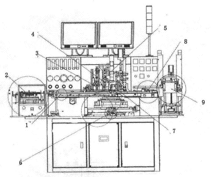
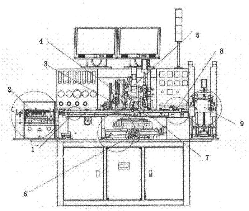
[0022] The method of the present invention is:

[0023] (1) Put the chip on the workbench, the machine will automatically support the film, make a template for the chip, and save the template to the device file;

[0024] (2) Put the lead frame on the loading table, the machine automatically sucks the material to the worktable through the suction cup, and transports it to the track protected by hydrogen and nitrogen through the transport hook;

[0025] (3) When the lead frame is transported to the fifth temperature zone, the wire feeding mechanism supplies tin wire to the frame;

[0026] (4) When the frame is transported to the sixth temperature zone, use a cemented carbide die head to press the solder point on the frame into a square shape;

[0027] (5) When the frame reaches the seventh temperature zone, the suction head sucks the chip from the blue film and welds it to the frame. W...


PUM


Abstract

The invention discloses a welding method and device for producing high-power tube chips. The purpose of the present invention is to provide a high-power tube chip welding method and device thereof, which have automatic production, high production efficiency, saving enterprise operating costs and stable product quality. The steps of the invention include mold making, material suction, wire feeding, pressing, core welding, heat preservation, cooling, stacking and the like, and the invention is mainly used in chip factories to produce power tube chips.

Description

technical field [0001] The invention relates to a welding method, in particular to a high-power transistor chip welding method and a device suitable for a series of frames such as TO-220, TO-3P-TO-247, and TO-251. Background technique [0002] High-power transistors are mainly used in switching power supplies for household appliances, such as color TVs, computers, induction cookers, etc., as well as automotive appliances, such as car igniters, etc., industrial appliances such as PLC power supplies, servo controllers, frequency converters, voltage regulators, choppers , DC welding machine and so on. High-power transistor chip welding generally uses a manual welding process. Manual welding chips are inefficient, and at the same time consume a lot of power, and the loss of protective gas (hydrogen and nitrogen gas) is correspondingly large, which increases operating costs, poor quality consistency, and low efficiency. Contents of the invention [0003] The invention disclose...

Claims


Application Information

Patent Timeline
Patent Type & Authority Applications(China)
IPC IPC(8): B23K1/00B23K3/00B23K3/08H01L21/60
CPCH01L2924/0002
Inventor 施金佑
Owner JIEYANG HONGGAN ELECTRONICS
Why Eureka
Try Eureka