Method and device for measuring dynamic light scattering nanoparticles based on band-pass filtering

A dynamic light scattering and nanoparticle technology, applied in measurement devices, particle and sedimentation analysis, particle size analysis, etc., can solve the problems of limiting particle size reliability, wrong particle size distribution, particle size distribution deviation, etc. Data processing time, fast measurement, and the effect of measurement

Inactive Publication Date: 2011-12-28
UNIV OF SHANGHAI FOR SCI & TECH
View PDF4 Cites 19 Cited by
  • Summary
  • Abstract
  • Description
  • Claims
  • Application Information

AI Technical Summary

Problems solved by technology

However, no matter the inversion based on the autocorrelation signal or the inversion based on the power spectrum signal, the coefficient matrix is ​​seriously ill-conditioned, such as Figure 5 As shown, a small measurement signal error will lead to a huge deviation of the particle size distribution, and even get a wrong particle size distribution
This limits the rel

Method used


Image

  • Method and device for measuring dynamic light scattering nanoparticles based on band-pass filtering
  • Method and device for measuring dynamic light scattering nanoparticles based on band-pass filtering
  • Method and device for measuring dynamic light scattering nanoparticles based on band-pass filtering

Examples


Embodiment 1

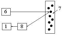
[0039] Example 1 (scattered light from particles is directly detected by a photodetector):

[0040] Depend on figure 2 As shown, it includes a semiconductor laser 6, a measurement area 7, a photodetector 8 and an analog circuit 1. The light beam emitted by the laser 6 irradiates the measurement area 7 . The light scattered by the particles in the measurement area 7 is received by the photodetector 8 , and finally the power spectral density function is obtained through the analog circuit 1 .

Embodiment 2

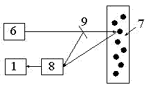
[0041] Example 2 (the scattered light of the particle interferes with part of the light of the original laser and is detected by the photodetector):

[0042] Depend on image 3 As shown, it includes a semiconductor laser 6, a beam splitter 9, a measurement area 7, a photodetector 8 and an analog circuit 1. The beam splitter 9 is placed between the laser 6 and the measurement area 7 , and the beam emitted by the laser 6 is split into two beams by the beam splitter 9 . One beam passes through the beam splitter and irradiates the measurement area 7; the other beam is reflected by the beam splitter as intrinsic light. The light scattered by the particles in the measurement area 7 interferes with the intrinsic light, and is detected by the photodetector 8 , and finally the power spectral density function is obtained through the analog circuit 1 .

Embodiment 3

[0043] Example 3 (the light scattered by the particles is fed back into the laser cavity, self-mixed, and then the laser output is modulated and detected by the photodetector):

[0044] Depend on Figure 4 As shown, it includes a semiconductor laser 6, a measurement area 7, a photodetector 8 and an analog circuit 1. The photodetector 8 is placed behind the laser 6, and the light beam emitted by the laser 6 is irradiated to the measurement area 7, and the backscattered light from the particles is fed back into the laser resonant cavity to mix with the original laser. The backward output light of the laser is detected by the photodetector 8, and finally the power spectral density function is obtained through the analog circuit 1.


PUM


Abstract

The invention discloses a method and an apparatus for measuring dynamic light scattering nano-particles based on bandpass filtering. According to the invention, lasers are radiated on nano-particles performing Brownian motions in a solution. The scattered lights of the particles are directly detected; or the scattered lights of the particles are interfered with part of the original lights, and are detected; or the scattered lights are fed-back into a laser-tube cavity, self mixing is occurred, and self mixing signals are detected. Signals output by a photoelectric detector are pre-amplified, and are simultaneously delivered into a circuit formed by components of an M route buffer, bandpass filters with different central frequencies, and an RMS root-mean-square processor, which are connected in series, such that signal root-mean-square values at different frequencies with a number of M are obtained. The values are sampled by an A/D collecting card, such that power spectrum density functions at different frequencies with a number of M are obtained. With the method and the apparatus provided by the invention, a problem in prior arts of poor robustness of inverse calculations caused by seriously ill-conditioned coefficient matrix is solved. With the method and the apparatus provided by the invention, requirements on data collecting speed, data collecting amount, storage amount andprocessing amount are reduced; data processing time is reduced; and rapid measuring of nano-particle sizes can be realized.

Description

technical field [0001] The invention relates to a method and device capable of measuring nanoparticles, in particular to a method and device for measuring dynamic light scattering nanoparticles based on band-pass filtering, and belongs to the field of measurement technology. It can be used in many fields involving nanoparticle production and process control, such as scientific research, biomedicine, chemical energy, environmental protection, etc. [0002] Background technique [0003] In the dynamic light scattering nanoparticle measurement technology, the autocorrelation function of the scattered light signal is obtained by a digital correlator or the power spectral density function of the scattered light signal is obtained by the power spectrum estimation method, and the particle size of the nanoparticle is obtained by matrix inversion. diameter distribution parameters. [0004] The laser light emitted by the laser is combined by a single or multiple lenses to form conve...

Claims


Application Information

Patent Timeline
IPC IPC(8): G01N15/02
Inventor 沈建琪王华睿
Owner UNIV OF SHANGHAI FOR SCI & TECH
Why Eureka
Try Eureka