
Top gas pressure recovery turbine generating system

A blast furnace gas and power generation system technology, which is applied in the field of blast furnace gas residual pressure turbine power generation system, can solve the problems of wasting blast furnace gas residual pressure energy, increase unit maintenance workload, economic losses, etc., so as to reduce system maintenance amount and improve use. efficiency, and the effect of increasing power generation

Active Publication Date: 2013-10-30
WISDRI ENG & RES INC LTD
View PDF4 Cites 0 Cited by
  • Summary
  • Abstract
  • Description
  • Claims
  • Application Information

AI Technical Summary

Problems solved by technology

Blast furnace gas dry dust removal has the advantages of high dust removal efficiency, water saving, and electricity saving, and fully retains the pressure energy and heat energy of blast furnace gas to increase the power generation of TRT. The acid gas that is easy to scale is removed, and salt accumulation is formed in the blast furnace gas pipeline, especially in the TRT turbine (mainly, the salt accumulation in the second-stage blade of the turbine and the exhaust volute is serious, and the thickness can reach 50 -60mm), the salt accumulation on the turbine rotor will cause the unit to vibrate, which will lead to serious accidents, so regular manual descaling is necessary. Basically, the turbine needs to be opened and cleaned once every one to two months, which not only increases the The maintenance workload of the unit also wastes a lot of residual pressure energy of blast furnace gas, which brings huge economic losses

Method used


Image

  • Top gas pressure recovery turbine generating system

Examples


Embodiment Construction

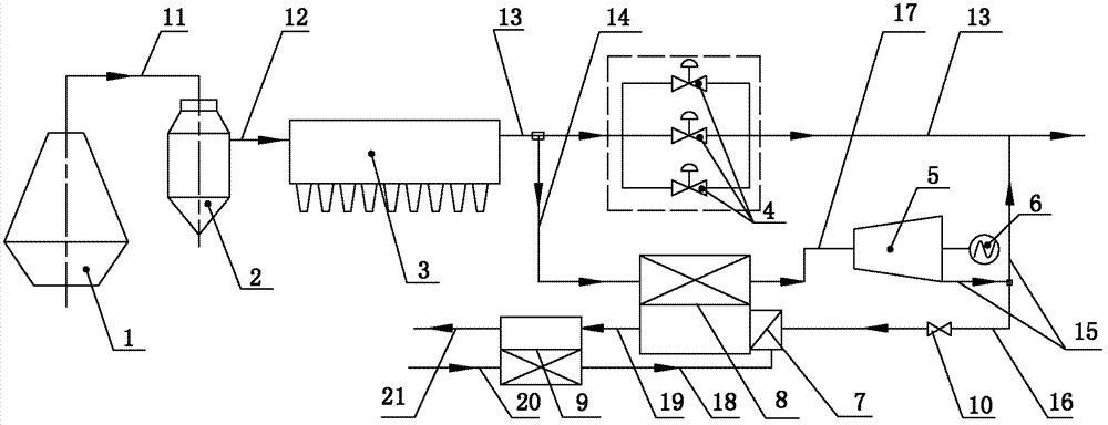
[0011] like figure 1 As shown, the blast furnace gas residual pressure turbine power generation system includes a gravity dust collector 2, a bag filter 3, a pressure reducing valve group 4, a turbine 5, a generator 6, a first pipeline 11, a second pipeline 12, a first pipeline Three pipelines 13, the fourth pipeline 14, the fifth pipeline 15; the input port of the gravity dust collector 2 is connected with the gas output port of the blast furnace 1 (ironmaking blast furnace) by the first pipeline 11, and the output port of the gravity dust collector 2 is connected by the first pipeline 11 The second pipeline 12 is connected with the input port of the bag filter 3, and the output port of the bag filter 3 is connected with the third pipeline 13. The third pipeline 13 is provided with a pressure reducing valve group 4, and the pressure reducing valve group 4 is connected with the bag filter The third pipeline 13 between the output ports of 3 communicates with the input end of th...


PUM


Abstract

The invention belongs to the technical field of dry dust removal of top gas and pressure recovery turbine generating, and particularly relates to a top gas pressure recovery turbine generating system. The top gas pressure recovery turbine generating system comprises a gravity dust remover, a bag type dust remover, a reducing valve bank, a turbine, an electric generator, a first pipeline, a second pipeline, a third pipeline, a fourth pipeline and a fifth pipeline. The top gas pressure recovery turbine generating system is characterized in that the output end of the fourth pipeline is communicated with a cold fluid input port of a heat exchanger, and a cold fluid output port of the heat exchanger is communicated with a gas inlet of the turbine through a seventh pipeline; the fifth pipeline is connected with the input end of a sixth pipeline through a three-way valve, the output end of the sixth pipeline is communicated with a gas input port of a burner, and the sixth pipeline is provided with a flow control valve; and an air input port of the burner is communicated with an eighth pipeline, hot gas generated by the burner enters a hot fluid input port of the heat exchanger, and a hot fluid output port of the heat exchanger is communicated with a ninth pipeline. The system can reduce or avoid salt deposit in the turbine.

Description

technical field [0001] The invention belongs to the technical field of blast furnace gas dry dust removal and residual pressure turbine power generation, and in particular relates to a blast furnace gas residual pressure turbine power generation system. Background technique [0002] Blast furnace gas dry dedusting and residual pressure turbine power generation (TRT) system is an essential energy recovery system for modern blast furnaces. Generally, 40-50% of the electric energy required by blast furnace blowers can be recovered, and the economic benefits are very significant. Blast furnace gas dry dust removal has the advantages of high dust removal efficiency, water saving, and electricity saving, and fully retains the pressure energy and heat energy of blast furnace gas to increase the power generation of TRT. The acid gas that is easy to scale is removed, and salt accumulation is formed in the blast furnace gas pipeline, especially in the TRT turbine (mainly, the salt acc...

Claims


Application Information

Patent Timeline
Patent Type & Authority Patents(China)
IPC IPC(8): C21B5/06
Inventor 盖东兴黄永红叶理德王虹胡建亮
Owner WISDRI ENG & RES INC LTD
Learn More