Method for in-situ full-field early detection of stainless steel pitting

An early detection, stainless steel technology, applied in measuring devices, weather resistance/light resistance/corrosion resistance, instruments, etc., can solve problems such as low resolution, inability to detect early pitting corrosion of stainless steel, inability to observe and detect local corrosion information of electrodes, etc., to achieve Intuitive Resolution Effects

Inactive Publication Date: 2012-01-11
NANCHANG HANGKONG UNIVERSITY
View PDF3 Cites 21 Cited by
  • Summary
  • Abstract
  • Description
  • Claims
  • Application Information

AI Technical Summary

Problems solved by technology

This method takes a long time to test, usually takes 24 hours to 72 hours, and cannot detect early pitting corrosion of stainless steel
Electrochemical measurement methods, such as steady-state method, transient method and AC impedance technology, take the whole electrode as the research object, use electrical signals (potential, current or charge) as excitation and detection means, and obtain relevant electrode processes through interpretation. Indirect, statistical and area average research information, this me...

Method used


Image

  • Method for in-situ full-field early detection of stainless steel pitting
  • Method for in-situ full-field early detection of stainless steel pitting
  • Method for in-situ full-field early detection of stainless steel pitting

Examples


Embodiment 1

[0022] Step 1: Sample preparation, first process 304 stainless steel into a disc with a diameter of 5 mm and a thickness of 4 mm. The metallographic sample mounting machine is used to encapsulate the stainless steel wafer (the mounting material is phenolic resin powder), and it is polished to 400# by water-grinding paper from coarse to fine, and the working surface of the sample is cleaned and degreased with acetone. After drying, it is short Store in a dry dish for later use.

[0023] Step 2: Prepare the experimental soaking solution. The experimental soaking solution is divided into indicator and bulk solution, wherein the indicator is mixed with component 1 and component 2 solutions, and component 1 is 10% potassium ferricyanide solution prepared with pure water , component 2 is obtained by dissolving phenolphthalein in alcohol, the concentration is 0.1 g / ml, the volume ratio of 50:1 component 1 and component 2 solution is mixed, and the indicator used in the experiment is ...

Embodiment 2

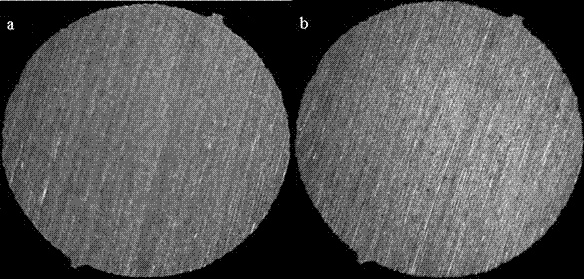
[0027] Except that water abrasive paper is polished to 800# from coarse to fine, other is the same as embodiment 1, and experimental result is as follows figure 2 As shown, the pitting corrosion time is 402 s.

Embodiment 3

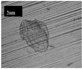
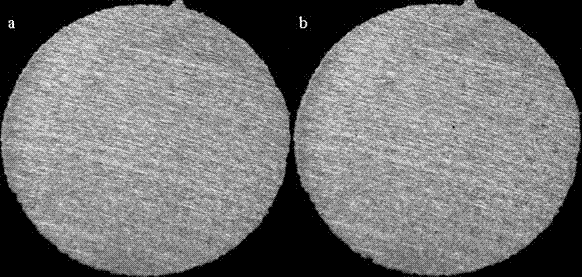
[0029] Except that the water abrasive paper is polished to 1200# from coarse to fine, other is the same as embodiment 1, and the experimental results are as follows image 3 As shown, the pitting time is 463 s. Metallographic observation of the corrosion pits revealed that the diameter of the corrosion pits was about 10 μm.


PUM


Abstract

The invention discloses a method for in-situ full-field early detection of stainless steel pitting. The method comprises the following steps of 1, carrying out packaging of a stainless steel sample and carrying out mechanical polishing of a working face of the stainless steel sample, 2, preparing an experimental soak solution, and 3, putting a beaker containing the experimental soak solution obtained by the step 2 into a constant-temperature water bath, finishing detection temperature setting, putting the stainless steel sample treated by the step 1 into the beaker in a way that the working face of the stainless steel sample is upward, simultaneously, carrying out an in-situ full-field observation process on the surface of the stainless steel sample by a long-distance microscope and a digital camera, wherein when a display shows that blue spots appear on the surface of the stainless steel sample, pitting occurs, and recording the time between putting-in and taking-out of the stainless steel sample. The method can realize rapid in-situ detection of stainless steel pitting. Pitting information which comprises stainless steel pitting positions, stainless steel pitting number, stainless steel pitting areas and stainless steel pitting occurrence time and can be detected by the method has important academic values and practical application values.

Description

technical field [0001] The invention relates to a method for detecting stainless steel pitting corrosion, in particular to a method for in-situ full-field detection of early stainless steel pitting corrosion. Background technique [0002] Stainless steel has excellent corrosion resistance due to the formation of a dense chromium oxide layer on the surface, so it can be widely used in modern industrial fields and daily life. However, while resisting uniform corrosion, localized pitting corrosion (ie, pitting corrosion) of stainless steel is unavoidable. Pitting corrosion is invisible and difficult to detect, but it is extremely destructive. If left unchecked, it will cause the stainless steel material to perforate until the entire structure is destroyed. Since the 1930s, humans have never stopped exploring the nucleation mechanism of stainless steel pitting corrosion, and pitting corrosion has become one of the classic problems in the field of materials science and engineeri...

Claims


Application Information

Patent Timeline
IPC IPC(8): G01N17/00G01N21/84
Inventor 王梅丰李光东
Owner NANCHANG HANGKONG UNIVERSITY
Why Eureka
Try Eureka