Dynamic balancing device and balancing method for battery pack

A technology of dynamic equalization and equalization device, applied in battery circuit devices, circuit devices, electric vehicles, etc., can solve the problems of weak equalization ability and large energy loss, and achieve the effect of low energy consumption, reduced requirements and increased capacity

Inactive Publication Date: 2012-01-11
谷涛
View PDF3 Cites 20 Cited by
  • Summary
  • Abstract
  • Description
  • Claims
  • Application Information

AI Technical Summary

Problems solved by technology

[0004] In order to overcome the shortcomings of weak balancing ability and large energy loss of the existing balancing method, the present invention designs a device for realizing dynamic balancing between single cells or sub-modules during the charging and discharging process of a series-parallel hybrid battery pack and provides a control and balancing device for the balancing The scheme of the device; the device can dynamically adjust the electrical connection mode between the single cells or sub-modules during the charging and discharging process, so that the battery pack can be adjusted to a state close to the ideal balance; the present invention does not need Energy is transferred between them, so the efficiency is high and the severely unbalanced battery pack can be balanced; the more single cells or sub-modules in parallel in the battery pack, the better the equalization effect after using the device designed by the present invention

Method used


Image

  • Dynamic balancing device and balancing method for battery pack
  • Dynamic balancing device and balancing method for battery pack
  • Dynamic balancing device and balancing method for battery pack

Examples


Embodiment 1

[0030] The dynamic balance of the battery pack is achieved by pushing the sliding connection block.

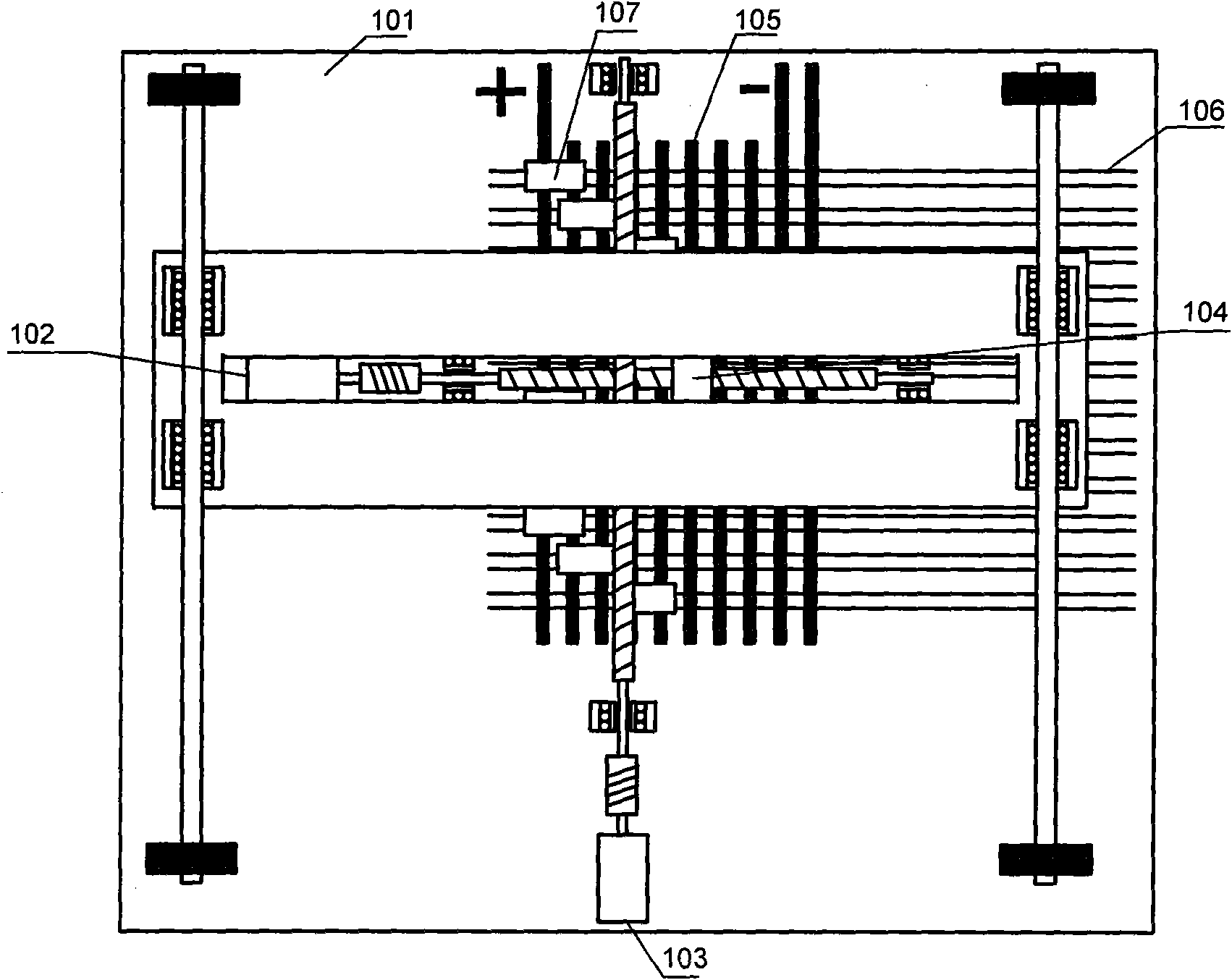
[0031] figure 1 It is the electromechanical dynamic balancing system diagram of the battery pack in Embodiment 1. The device includes an insulating base plate (101), a lateral positioning system (102), a longitudinal positioning system (103), an electromagnet (104), a bus connection (105), a single battery or a sub-module connection (106), and a sliding Connection blocks (107). The insulating bottom plate (101) is the basic structural component of the system, and other components are directly or indirectly supported and fixed by it.

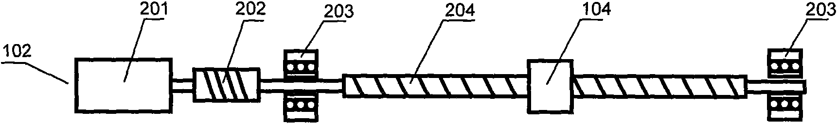
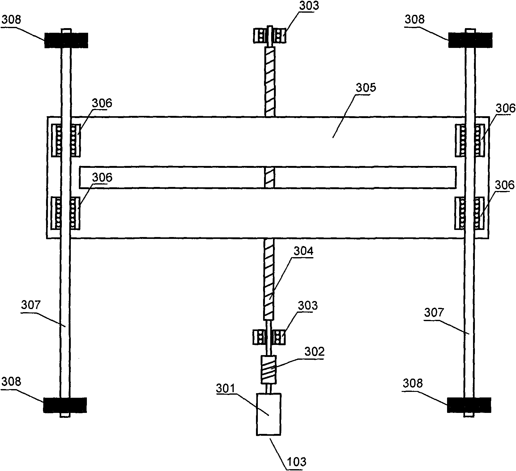
[0032] figure 2 shown as figure 1 The horizontal positioning system in the middle is composed of a stepper motor (201), a shaft coupling (202), a bearing (203), a screw rod (204) installed on the bearing (203), and is supported by a horizontal system bearing plate (305). Chute restriction can not rotate the electromagnet (104) that can only...

Embodiment 2

[0052] The dynamic balance of the battery pack is realized by switching the matrix switch.

[0053] Figure 5 It is the dynamic balancing system diagram of the battery pack relay matrix in embodiment 2. The system includes an insulating base plate (101), a bus connection (105), a positive connection (401), a negative connection (402), a spare connection (403), a single battery or a sub-module positive connection (106), Single battery or sub-module negative connection (404), and double pole single throw relay (501). Parts with the same numerals are the same or similar to those described in Embodiment 1. Double-pole single-throw relay (501) has such an effect that when it is closed, it connects the two poles of the corresponding single battery or sub-module with the adjacent two bus lines and always connects the two poles of the single battery or sub-module. The positive connection (106) is connected to the far left (that is, the higher potential) bus connection (105) in the ...

Embodiment 3

[0062] The dynamic balance of the battery pack is realized through the integrated circuit.

[0063] Image 6 It is the module diagram of the battery pack dynamic balance integrated circuit in embodiment 3. The circuit includes a load positive confluence connection (601), a load negative confluence connection (602), a spare connection (603), an inter-level confluence connection (604), a controllable switch node (605), a single battery or Sub-module positive connection (606), single battery or sub-module negative connection (607), communication port connection (608) and (609), voltage monitoring circuit (610), decoding circuit (611) (controlling all possible control switch node (605)), chip power supply (612), ground terminal (613), and power supply circuit (614).

[0064] Figure 7 is a typical structure of each controllable open-close node (605). It includes a field effect transistor (701), a drain connection (703), a source connection (704), a gate connection (705), and a...


PUM


Abstract

The invention discloses a dynamic balancing device for balancing a battery pack in charging or discharging. The dynamic balancing device overcomes the defects that in the existing balancing device, the energy consumption is more and the balancing capability is weak. The device adopts the technical scheme that an electric connecting mode among all single batteries or submodules in the battery pack is changed dynamically, i.e., the series-parallel state of the single batteries or the submodules in the battery pack is changed, so that the purpose of leading the battery pack to tend to be balanced is achieved. During discharging, the voltage of each level in the battery pack is acquired. When the voltage difference is large, one single battery is pushed to the level with lowest voltage from the level with highest voltage; and when the voltage difference is small, a plurality of single batteries or the submodules are connected with different levels in a time-sharing manner, the time for parallel connection with the levels with lower voltages is longer, and the proportional integral and differential adjustment can be carried out on the specific time according to all levels of voltages so as to lead the battery pack to tend to be completely balanced.

Description

technical field [0001] The invention relates to a battery pack dynamic equalization device and a battery pack dynamic equalization method. More specifically, it is a method of dynamically connecting single cells or sub-modules to different levels of the battery pack to achieve capacity balance between levels, which is mainly used in the field of power battery technology. Background technique [0002] The voltage and capacity of a single battery generally cannot meet the needs of a power source, so multiple single batteries must be connected in series and parallel to form a battery pack to provide electrical energy. Sometimes several single cells are connected and packaged together to form a sub-module during the manufacturing process. These sub-modules can be further connected in series and parallel like single cells. Assume that a battery pack contains n by m single cells or sub-modules, in which every m single cells or sub-modules are first connected in parallel, and a p...

Claims


Application Information

Patent Timeline
Patent Type & Authority Applications(China)
IPC IPC(8): H02J7/00
Inventor 谷涛
Owner 谷涛
Why Eureka
Try Eureka