High voltage generator, X ray generation device and control method thereof

A high-voltage generator and X-ray tube technology, applied in the field of X-ray control, can solve the problem of high consistency requirements, and achieve the effect of improving adaptability, flexibility and diversity

Active Publication Date: 2017-05-31
SHANGHAI UNITED IMAGING HEALTHCARE +1
View PDF11 Cites 8 Cited by
  • Summary
  • Abstract
  • Description
  • Claims
  • Application Information

AI Technical Summary

Problems solved by technology

[0005] The technical problem to be solved by the present invention is to provide an X-ray high-voltage generator with cathode and anode voltage balance capabilities, which overcomes the high consistency requirements of the existing cathode and anode balance structure for high voltage generators and poor ability to adapt to unbalanced loads The problem

Method used


Image

  • High voltage generator, X ray generation device and control method thereof
  • High voltage generator, X ray generation device and control method thereof
  • High voltage generator, X ray generation device and control method thereof

Examples


Embodiment 1

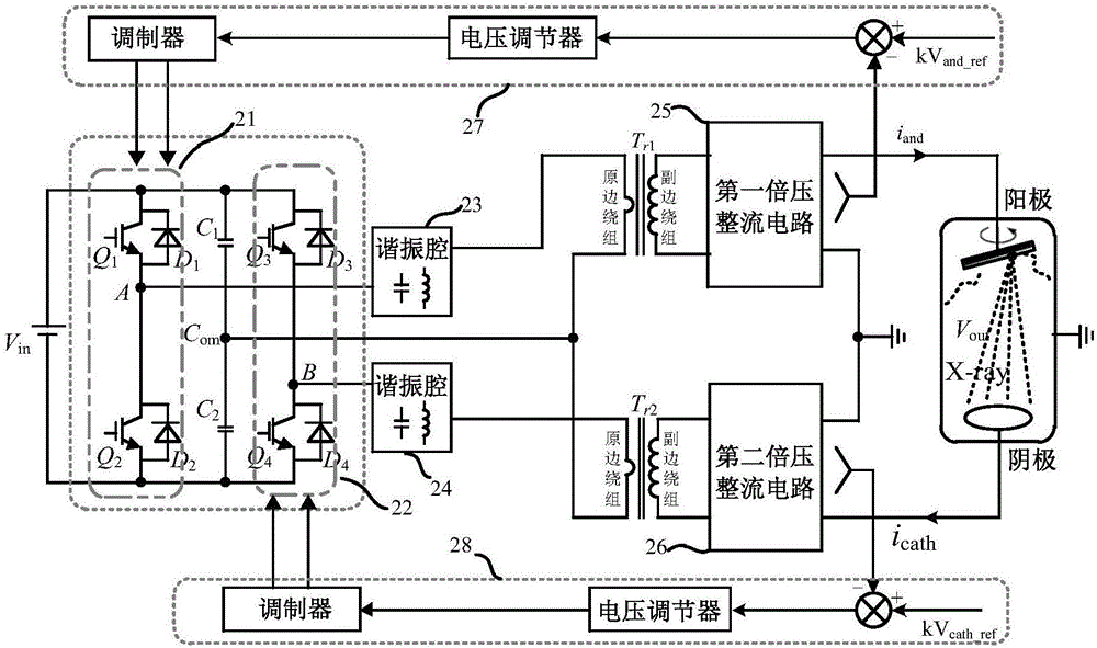
[0047] figure 2 It is a schematic diagram of the circuit structure of an X-ray high voltage generator according to an embodiment of the present invention. The high-voltage generator includes an inverter (circuit), a resonant cavity, a transformer, a voltage doubler rectifier circuit and control components.

[0048] The inverter circuit is composed of a first switching device Q1, a second switching device Q2, a third switching device Q3, a fourth switching device Q4, a first capacitor C1, and a second capacitor C2. Wherein, the first switching device Q1 and the second switching device Q2 are connected in series to form a first bridge arm (leading bridge arm) 21; the third switching device Q3 and the fourth switching device Q4 are connected in series to form a second bridge arm (lag bridge arm) 22; The first capacitor C1 and the second capacitor C2 are connected in series to form a third bridge arm (common bridge arm), and the third bridge arm is arranged between the first bri...

Embodiment 2

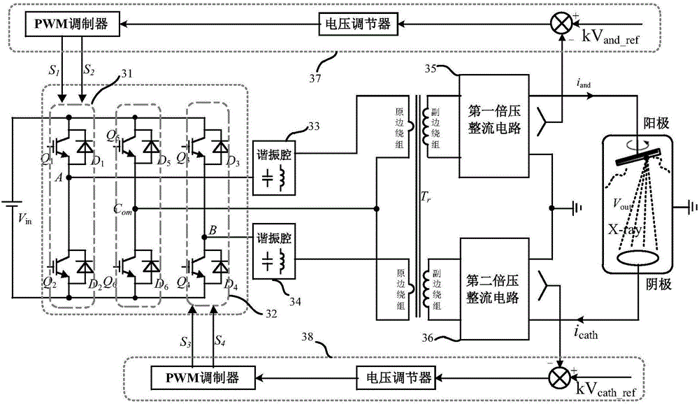
[0067] The difference between this embodiment and the first embodiment lies in that the third bridge arm includes active devices. Such as image 3 Shown is the schematic diagram of the circuit structure of the X-ray high voltage generator of the second embodiment, the third bridge arm (common bridge arm) of the inverter circuit includes the fifth switching device Q5 and the sixth switching device Q6 connected in series, in the fifth switch A reverse diode D5 is connected in parallel at both ends of the device Q5, a reverse diode D6 is connected in parallel at both ends of the sixth switching device Q6, and the midpoint Com of the third bridge arm is electrically connected to the transformer T r output terminal of the primary winding. The modulator contained in the first control component 37 is a PWM modulator, and the modulator contained in the second control component 38 is a PWM modulator. It should be noted that the transformer used in this embodiment is a transformer wit...

Embodiment 3

[0083] The difference between this embodiment and the second embodiment lies in the control mode of each switching device in the inverter circuit. Such as Figure 5 As shown, the modulator contained in the first control component 57 is a PFM modulator, the modulator contained in the second control component 58 is a PWM modulator, and a frequency synchronization circuit 59 is connected between the PFM modulator and the PWM modulator. The PFM modulator connects the base poles of the switching devices in the first bridge arm 51 and the third bridge arm simultaneously, and performs PFM modulation on the first bridge arm 51 and the third bridge arm; the PWM modulator connects the switching devices in the second bridge arm 52 The base is used to perform PWM modulation on the second bridge arm 51 , and the frequency synchronization circuit 59 adjusts the adjustment frequency or operating frequency of the PWM modulator and the PFM modulator to be the same.

[0084] The anode inverter...


PUM


Abstract

The invention provides a high voltage generator which comprises an inverter which comprises a first bridge arm, a second bridge arm, and a third bridge arm between the first bridge arm and the second bridge arm. The first bridge arm and the second bridge arm comprise two switch devices, an anode inverter bridge can be formed by the first bridge arm and the third bridge arm, a cathode inverter bridge can be formed by the second bridge arm and the third bridge arm, the anode inverter bridge adjusts the anode voltage of the high voltage generator, and the cathode inverter bridge adjusts the cathode voltage of the high voltage generator. The high voltage generator also comprises a first control component which is used for controlling the switch device of the anode inverter bridge, the input end of the first control component is connected to the anode of the high voltage generator, and the output end is connected to the first bridge arm. The high voltage generator also comprises a second control component which is used for controlling the switch device of the cathode inverter bridge, the input end of the second control component is connected to the cathode of the high voltage generator, and the output end is connected to the second bridge arm. The cathode and anode of the high voltage generator are controlled individually, and the adaption ability to an unbalanced load is improved. In addition, the invention provides an X ray generation device and a control method thereof.

Description

technical field [0001] The present invention mainly relates to X-ray control technology, and in particular to a high-voltage generator used in an X-ray generating device, an X-ray generating device and a control method for the X-ray generating device. Background technique [0002] X-ray generating devices such as X-ray tubes are often used in X-ray therapy equipment, X-ray diagnostic equipment, X-ray computed tomography (CT), positron emission computed tomography (PET-CT) and other medical equipment. In the process of using an X-ray tube to emit X-rays, the cathode filament is usually suspended at a potential of -70kV ~ -75kV, the anode target disk is suspended at a potential of +70kV ~ +75kV, and the shell is grounded at the same time, which can reduce the X-ray tube. Insulation requirements, reducing the size and cost of the X-ray tube. However, when this kind of X-ray tube with cathode and anode potential suspension is working, because the filament is heated and emits el...

Claims


Application Information

Patent Timeline
Patent Type & Authority Applications(China)
IPC IPC(8): H01J35/02
CPCH01J35/025
Inventor 祝国平褚旭
Owner SHANGHAI UNITED IMAGING HEALTHCARE
Why Eureka
Try Eureka