Reinforcing method of masonry arch bridge

A technology for masonry arch bridges and arch bridges, used in bridge reinforcement, arch bridges, bridges, etc., can solve problems such as damage to the integrity of the original stone masonry arch ring, affecting the joint work effect, and insignificant improvement effect, so as to shorten the construction period and achieve good integrity. , The effect of reducing the difficulty of construction

Inactive Publication Date: 2013-08-07
CHONGQING JIAOTONG UNIVERSITY
View PDF4 Cites 2 Cited by
  • Summary
  • Abstract
  • Description
  • Claims
  • Application Information

AI Technical Summary

Problems solved by technology

The effect of pasting steel plates or fiber cloth on arch rings mainly under compression is not obvious, and the surface weathering of stone arch rings obviously affects the joint work effect of steel plates or fiber cloth with original arch rings; the full bridge width above or below the arch rings Adding a certain thickness of reinforced concrete can increase the bearing capacity by enlarging the cross-sectional area, but the large-area planted reinforcement will seriously damage the integrity of the original stone arch ring, and the actual improvement of the bearing capacity needs to consider the reduction of the original stone arch ring due to the damage of the planted reinforcement
The method of adding reinforced concrete hoops around the arch ring can also increase the bearing capacity by increasing the cross-sectional area. However, due to the large concrete area, the newly added concrete produces a large self-weight, so usually only the arch ring is installed in sections to reduce the amount of concrete. , but the segmental setting will cause the sudden change section to become the weak point of the reinforced arch ring

Method used


Image

  • Reinforcing method of masonry arch bridge
  • Reinforcing method of masonry arch bridge
  • Reinforcing method of masonry arch bridge

Examples


Embodiment Construction

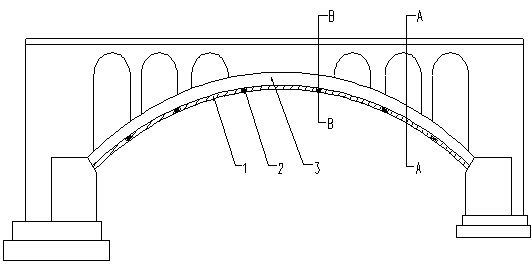
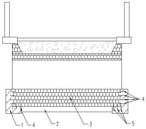
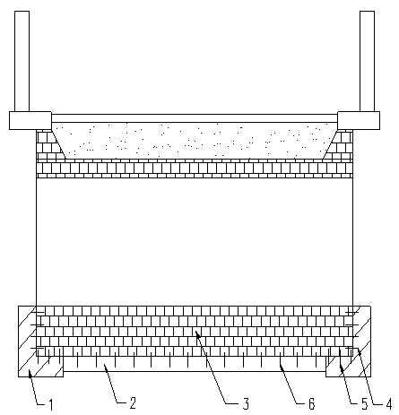
[0018] figure 1 It is a structural schematic diagram of the arch bridge reinforced by the method of reinforcement of the present invention; figure 2 for figure 1 A cross-sectional view along the direction A—A; image 3 for figure 1 The sectional view along the direction of B-B. As shown in the figure, the reinforcement method of the masonry arch bridge of the present embodiment comprises the following steps:

[0019] a, implant steel bars 4 on both sides of the arch ring 3 of the arch bridge along the arc direction of the arch bridge;

[0020] B, along the arc direction of the arch bridge, implant steel bars 5 on the arc surface of the arch ring 3 near the two sides;

[0021] c. Forming reinforced concrete ribs 1 with an L-shaped cross-section and symmetrical distribution along the direction of the planting reinforcement distribution in steps a and b by pouring molding.

[0022] By planting bars and pouring concrete, new reinforced concrete ribs forming an integrated st...


PUM


Abstract

The invention discloses a reinforcing method of a masonry arch bridge, which comprises the following steps of: a, planting ribs on an arch ring of the arch bridge along the cambered surface direction of the arch bridge; b, planting ribs at the position close to the two sides, on the circular arc surface of the arch ring along the cambered surface direction of the arch bridge; and c, forming symmetrically distributed reinforced concrete ribs along the distribution direction of the planted ribs in the step a and the step b in a way of casting molding, wherein the cross section of the reinforcedconcrete ribs is L-shaped. The reinforced concrete ribs which are of integral structures are formed along the two sides of the arch ring in the way of planting the ribs and casting concrete, then load can be directly transferred to an arch base through the symmetrically distributed reinforced concrete ribs of which the cross section is L-shaped, and the stress to the reinforced concrete ribs is equal to that to a ribbed arch bridge. When the method is compared with the method of singly increasing the area of the arch ring, the dependence on the primary arch ring is smaller, even the primary arch ring can be supported, the damage to the primary arch ring is small, the requirement of increasing the loading capacity of the masonry arch bridge is met, and the damage to the primary old arch ring is avoided to the maximal degree.

Description

technical field [0001] The invention relates to the field of bridge construction, in particular to a method for reinforcing masonry arch bridges. Background technique [0002] With the passage of time, a considerable number of masonry arch bridges are currently damaged due to erosion and corrosion of river water, changes in the external environment, increased live loads, weathering of stone materials, etc. , or due to the need to increase the bearing capacity of existing arch bridges due to the increase in traffic requirements, a large number of masonry arch bridges need to repair and transform the main arch or abdominal arch to eliminate potential safety hazards. In the prior art, for the lack of bearing capacity of the main arch ring, there are reinforcements such as pasting steel plates or fiber cloth, or adding a certain thickness of reinforced concrete to the entire bridge width above or below the arch ring, or adding reinforced concrete hoops around the arch ring. met...

Claims


Application Information

Patent Timeline
Patent Type & Authority Patents(China)
IPC IPC(8): E01D22/00E01D4/00E01D101/22E01D101/24
Inventor 范亮高燕梅
Owner CHONGQING JIAOTONG UNIVERSITY
Why Eureka
Try Eureka