Discontinuous multi-strand spiral flow baffle plate shell-and-tube heat exchanger

A shell-and-tube heat exchanger and baffle technology, which is applied in the direction of heat exchanger shell, heat exchange equipment, lighting and heating equipment, etc., can solve the problem of rising pressure drop of shell side resistance, large pressure drop, and reduced heat transfer efficiency. and other problems, to achieve the effect of reducing fluid resistance pressure drop, reducing manufacturing cost, and high membrane heat transfer coefficient

Inactive Publication Date: 2012-01-18
THE CHALLENGE PETROCHEM MACHINERY CORP
View PDF6 Cites 8 Cited by
  • Summary
  • Abstract
  • Description
  • Claims
  • Application Information

AI Technical Summary

Problems solved by technology

[0006] (1) Due to the tortuous flow of the shell-side fluid between the baffles and the change of the flow direction many times, it is easier to generate fluid separation at the edge of the baffles, thus increase flow resistance;
[0007](2) Due to the dead zone of flow stagnation at the intersection between the arcuate baffle and the shell, the heat transfer efficiency is reduced, and the heat transfer performance is also reduced. Easy to scale;
[0008](3) Since the fluid in the circular area of ​​the arcuate baffle flows parallel to the axis of the tube bundle, the heat transfer performance decreases;
[0010](5) When the inlet and outlet pipes on the shell side are far away from the tube sheet, since the flow stagnation dead zone will become larger, it is necessary to add an external accessory guide tube, At the same time, it is necessary to increase the effective length of the heat exchange tube;
[0011](6) Due to the two fatal shortcomings of vibration failure and large pressure drop, the development of large-scale cold and heat exchange equipment with bow-shaped baffles is difficult to overcome obstacles;
[0022]However, measures such as adding baffles and coupling blocks cannot significantly improve the heat transfer performance of the shell-and-tube heat exchanger, but instead make the resistance pressure drop along the shell side sharp rise

Method used


Image

  • Discontinuous multi-strand spiral flow baffle plate shell-and-tube heat exchanger
  • Discontinuous multi-strand spiral flow baffle plate shell-and-tube heat exchanger
  • Discontinuous multi-strand spiral flow baffle plate shell-and-tube heat exchanger

Examples


Embodiment 1

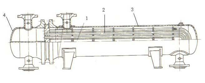
[0058] One of the specific implementations of a discontinuous multi-strand spiral flow baffle shell-and-tube heat exchanger of the present invention, refer to figure 1 As shown, it includes a tube bundle 2, a tube shell 3 and a tube box 4. The tube bundle 2 includes a heat exchange tube 1, a spiral flow baffle, a distance tube (not shown in the figure) and a tube sheet 6. The heat exchange tube 1 is The rows pass through the spiral flow baffles, and the two ends of the heat exchange tubes 1 penetrate into the tube holes of the tube sheet 6 and are connected with the tube sheet 6. The above technical features are the same as those of the spiral flow baffle tubes in the prior art. Shell heat exchangers have the same structure. The shell-and-tube heat exchanger also has other basic structures of the shell-and-tube heat exchanger in the prior art. The improvement of the present invention is that, with reference to Figure 7 As shown, the helical flow baffles include two or more ...

Embodiment 2

[0076] The second specific embodiment of a discontinuous multi-strand spiral flow baffle shell-and-tube heat exchanger of the present invention, the main technical solution of this embodiment is the same as that of embodiment 1, and the unexplained features in this embodiment, The explanation in Embodiment 1 is adopted, and details are not repeated here. The difference between this embodiment and Embodiment 1 is that an opening interval is provided between two adjacent fan-shaped baffles in the fan-shaped baffle group along the circumferential direction of the tube bundle . For the same tube bundle, the opening spacing in each group of fan-shaped baffles Can be set the same, or adjusted to , ... etc. different opening intervals . For different tube bundles, the opening spacing in each tube bundle The settings may be the same or different.

[0077] Specifically, the opening intervals in each fan-shaped baffle group set on the same line. And the straight line is ...

Embodiment 3

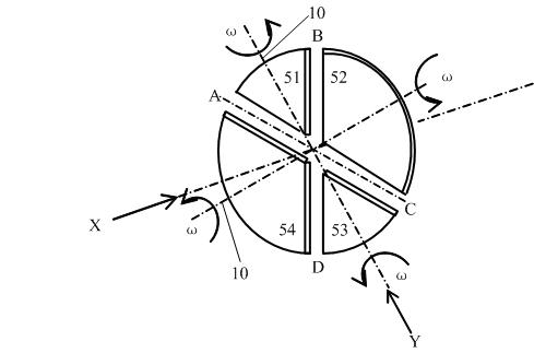
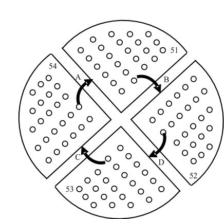
[0085] The third embodiment of a discontinuous multi-strand spiral flow baffle shell-and-tube heat exchanger of the present invention is as follows: Figure 7 As shown, the main technical solutions of this embodiment are the same as those of Embodiment 2, and the features not explained in this embodiment are explained in Embodiment 1, and will not be repeated here. The difference between this embodiment and Embodiment 2 is that there are six groups of fan-shaped baffles in this embodiment, each group of fan-shaped baffles includes three fan-shaped baffles, and the two groups of fan-shaped baffles Take a solid line B1-B2 and a dotted line A1-A2 with arrows on the flow plate group as an example, specifically marking the two helical flow path trajectories of the shell-side fluid of the tube bundle, in which the B1 section and A1 section are the main helical flow , Sections B2 and A2 are very short, or almost non-existent direct currents along the axial direction. The overall heli...


PUM


Abstract

The invention discloses a discontinuous multi-strand spiral flow baffle plate shell-and-tube heat exchanger, which comprises a tube bundle, a tube shell and a tube box, wherein the tube bundle comprises heat exchange tubes, spiral flow baffle plates, distance tubes and tube plates; the heat exchange tubes pass through the spiral flow baffle plates in a row, and the two ends of the heat exchange tubes pass through tube holes of the tube plates and are connected with the tube plates; and the spiral flow baffle plates comprise two or more than two fan-shaped baffle plate groups, and the fan-shaped baffle plate groups are discontinuously distributed or partially discontinuously distributed and partially continuously distributed in the axis direction of the tube bundle. Compared with the prior art, the heat exchanger has the advantages that: technical prejudice is overcome; multiple discontinuously distributed fan-shaped baffle plate groups form multi-group discontinuous multi-strand spiral flow to realize reinforced heat transfer of the heat exchange tubes; the heat exchanger has the characteristics of low fluid resistance, high film heat transfer coefficient and good heat exchange efficiency; and the assembly quality of the tube bundle can be improved, the energy is saved, and meanwhile, the spiral flow baffle plate tube bundle with large shell diameter can be adopted.

Description

technical field [0001] The present invention relates to shell and tube heat exchanger technology in equipment engineering, in particular to a discontinuous multi-strand spiral flow baffle specially used for heat exchange in petrochemical industry, coal chemical industry, chemical fertilizer industry, air conditioning and refrigeration, and electric power facilities Shell and tube heat exchanger. Background technique [0002] In the prior art, the shell-and-tube heat exchanger is the most widely used heat exchanger. The shell-and-tube heat exchanger is also called the shell-and-tube heat exchanger or the shell-and-tube condenser, which is widely used in chemical industry, petroleum Convective heat transfer of "liquid-liquid", "steam-steam", "steam-liquid" heat exchange in the fields of medicine, food, light industry, metallurgy, coking, etc., as well as steam condensation and liquid evaporation heat transfer Wait for the heat exchange and condensation process. [0003] The ...

Claims


Application Information

Patent Timeline
Patent Type & Authority Applications(China)
IPC IPC(8): F28F9/24
Inventor 陈孙艺
Owner THE CHALLENGE PETROCHEM MACHINERY CORP
Why Eureka
Try Eureka