Laser detection device and method for gear parameters

A laser detection and gear technology, which is used in the parameter detection of external gears, worm gears and worms, gear parameter laser detection devices, gear cutters, and internal gears. , to achieve the effect of improving detection speed, reducing measurement error and improving measurement accuracy

Inactive Publication Date: 2012-01-18
唐大春
View PDF9 Cites 69 Cited by
  • Summary
  • Abstract
  • Description
  • Claims
  • Application Information

AI Technical Summary

Problems solved by technology

The main disadvantages of comparative measurement are: the measurement accuracy depends on the accuracy of the standard part or the generated mechanism, the mechanical structure is complex, the flexibility is poor, and the same gear needs multiple instruments to measure
[0011] From the point of view of the probe, the CNC coordinate measurement method usually uses an inductive or grating contact probe. The main disadvantages are: 1. There is a sharp angle error, which makes it impossible to sample parts such as the tooth root of the gear. 2. The data sampling rate is low. The gear measuring machine with a contact probe cannot achieve full-section sampling of the tooth profile section, and can only perform discrete sampling at specific angles, such as 0°, 90°, 180°, 270° and other angle positions. Third, the measurement efficiency is low. The data processing speed of the gear measuring machine using the contact probe is slow, usually 50Points/s, and it takes 8 minutes to complete a measurement at the fastest, which cannot meet the requirements of online measurement; 4. The contact measurement will scratch the tooth surface, and it will be damaged due to Measuring force causes the tooth surface to bend and deform, which aff

Method used


Image

  • Laser detection device and method for gear parameters
  • Laser detection device and method for gear parameters
  • Laser detection device and method for gear parameters

Examples


Embodiment 1

[0065] Example 1: Parameter detection of large internal gear

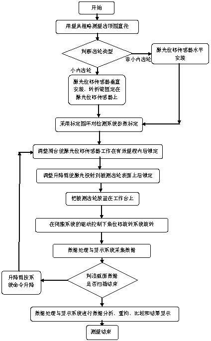
[0066] For large internal gears, press image 3 Step measurement:

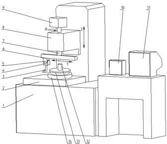
[0067] 1) First, roughly measure the tooth tip diameter and gear thickness of the measured gear 14 with a measuring tool and input them into the data processing and display system 11 for the laser displacement sensor 4 to determine the amount of expansion and contraction on the sliding table 6 and the lifting arm 8 Drive the lift of the sliding table 6;

[0068] 2) According to the rough measurement, the gear type is the large internal gear, small internal gear or external gear. If it is larger than 120mm, it is a large internal gear. Only the 120mm±10mm produced by Keyence Corporation of Japan that is compatible with the measurement of the large internal gear is installed. The laser displacement sensor does not need to install a turning mirror.

[0069] 3) and press Figure 7 The calibration detection of the large internal gear is shown, that is, the ca...

Embodiment 2

[0094] Example 2: Detection of small internal gear parameters

[0095] For the small internal gear, press image 3 Step measurement:

[0096] 1) First, roughly measure the tooth tip diameter and gear thickness of the measured gear 14 with a measuring tool and input them into the data processing and display system 11 for the laser displacement sensor 4 to determine the amount of expansion and contraction on the sliding table 6 and the lifting arm 8 Drive the lift of the sliding table 6;

[0097] 2) According to the gear type, it is a large internal gear, a small internal gear or an external gear, such as a small internal gear less than 120mm, such as Figure 4 The shown light path turning mirror and the laser displacement sensor are rigidly connected to the bracket 5 to realize synchronous rotation with the laser displacement sensor; the reflection surface of the turning mirror and the beam emitted by the laser displacement sensor are 45°, and the measuring surface formed by the meas...

Embodiment 3

[0125] Example 3: External gear parameter detection

[0126] For external gear, press image 3 Step measurement:

[0127] 1) First, roughly measure the tooth tip diameter and gear thickness of the measured gear 14 with a measuring tool and input them into the data processing and display system 11 for the laser displacement sensor 4 to determine the amount of expansion and contraction on the sliding table 6 and the lifting arm 8 Drive the lift of the sliding table 6;

[0128] 2) According to the gear type on the thick side, which is large internal gear, small internal gear or external gear, such as external gear, only the laser displacement sensor that matches with the external gear is installed, and no turning mirror is required.

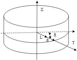
[0129] 3) and press Figure 7 The calibration test of the external gear is shown, that is, the calibration ring is used to calibrate the parameters of the detection system; the laser displacement d(t), the linear displacement z(t) of the lifting arm, the ...


PUM

PropertyMeasurementUnit
Circle diameteraaaaaaaaaa
Diameteraaaaaaaaaa

Abstract

The invention relates to a laser detection device and method for gear parameters. The laser detection device is characterized in that a worktable is provided with an internal point; a laser displacement sensor is arranged on a bracket; the bracket is arranged on a linear motor sliding block of a sliding table; the sliding table is arranged on an angular displacement rotating system and is fixedlyconnected to a rotating disk together with a rotating shaft; a casing of the angular displacement rotating system is arranged on a lifting arm through screws; the lifting arm is connected with the vertical surface of a machine body through a high-precision linear guide rail and a sliding block; a servo motor drives a ball screw which is fixedly connected to the vertical surface of the machine body to rotate; and a data acquisition and communication system is arranged on a rotating shaft upper plane of the angular displacement rotating system. Tested workpieces are subjected to data measurement, acquisition, transmission, reconstruction, separation, comparison and display to finish the full process of detection. According to the laser detection device and method, the non-contact and blind spot-free measurement is realized, the detection speed and measurement precision are improved; the difficult problem that a pinion is difficult to detect is solved; and in the measuring process, the gear is stationary and a measuring head does measuring movement, thus the measuring error caused by mounting the gear is reduced.

Description

technical field [0001] The invention relates to a gear parameter laser detection device and method, in particular to a parameter detection method of an external gear, an internal gear, a gear cutter, and a worm gear, and belongs to the technical field of gear precision measurement. Background technique [0002] The current gear parameter detection methods can basically be divided into four types, mechanical geometric analysis measurement method, gear meshing rolling comprehensive measurement method, CNC coordinate measurement method and non-contact gear measurement method. [0003] 1. Mechanical geometric analysis measurement method [0004] This method is mainly based on comparative measurement, and its essence is relative measurement. There are two specific methods: one is to compare the measured gear with a standard gear in kind, so as to obtain various errors; the other is to generate the measurement method, which is to compare the standard characteristic line formed b...

Claims


Application Information

Patent Timeline
IPC IPC(8): G01B11/00G01B11/02
CPCG01B11/2416
Inventor 唐大春苏成志王德民
Owner 唐大春
Why Eureka
Try Eureka