
Measured object image splicing method based on optical projection tomographic imaging system

A technology of optical projection tomography and projected images, which is applied in image data processing, 2D image generation, material analysis through optical means, etc. It can solve image blurring in spliced ​​areas, increased calculation cost, and little change in grayscale of projected images, etc. problems, to achieve the effect of saving computing resources and reducing the amount of computation

Inactive Publication Date: 2012-01-18
XIDIAN UNIV
View PDF4 Cites 12 Cited by
  • Summary
  • Abstract
  • Description
  • Claims
  • Application Information

AI Technical Summary

Problems solved by technology

At this time, the method based on the transform domain is required to search the entire image space at the same time, and the computational cost increases accordingly.
However, the method based on image features and the method directly based on image grayscale often have little change in the grayscale of the projected image itself, and the texture is not obvious, resulting in obvious stitching traces of the image or blurred images in the stitching area.

Method used


Image

  • Measured object image splicing method based on optical projection tomographic imaging system
  • Measured object image splicing method based on optical projection tomographic imaging system
  • Measured object image splicing method based on optical projection tomographic imaging system

Examples


Embodiment Construction

[0026] Various details involved in the technical solution of the present invention will be described in detail below in conjunction with the accompanying drawings. It should be pointed out that the described embodiments are only intended to facilitate the understanding of the present invention, rather than limiting it in any way.

[0027] The objects to be imaged by the OPT system generally include small animal embryos, organs, fruit flies, nematodes and other transparent or translucent objects in the range of 1-10mm.

[0028] In this embodiment, the small intestine of small animals is used as the measured object, but not limited thereto. A laser is used as the irradiation source, and a telecentric lens is used to irradiate the small intestine of small animals with light beam expansion into parallel light, and a high-sensitivity CCD camera is used. To collect projection images of the small intestine of small animals, the image size is 500×500 pixels, and a projection image is ...


PUM


Abstract

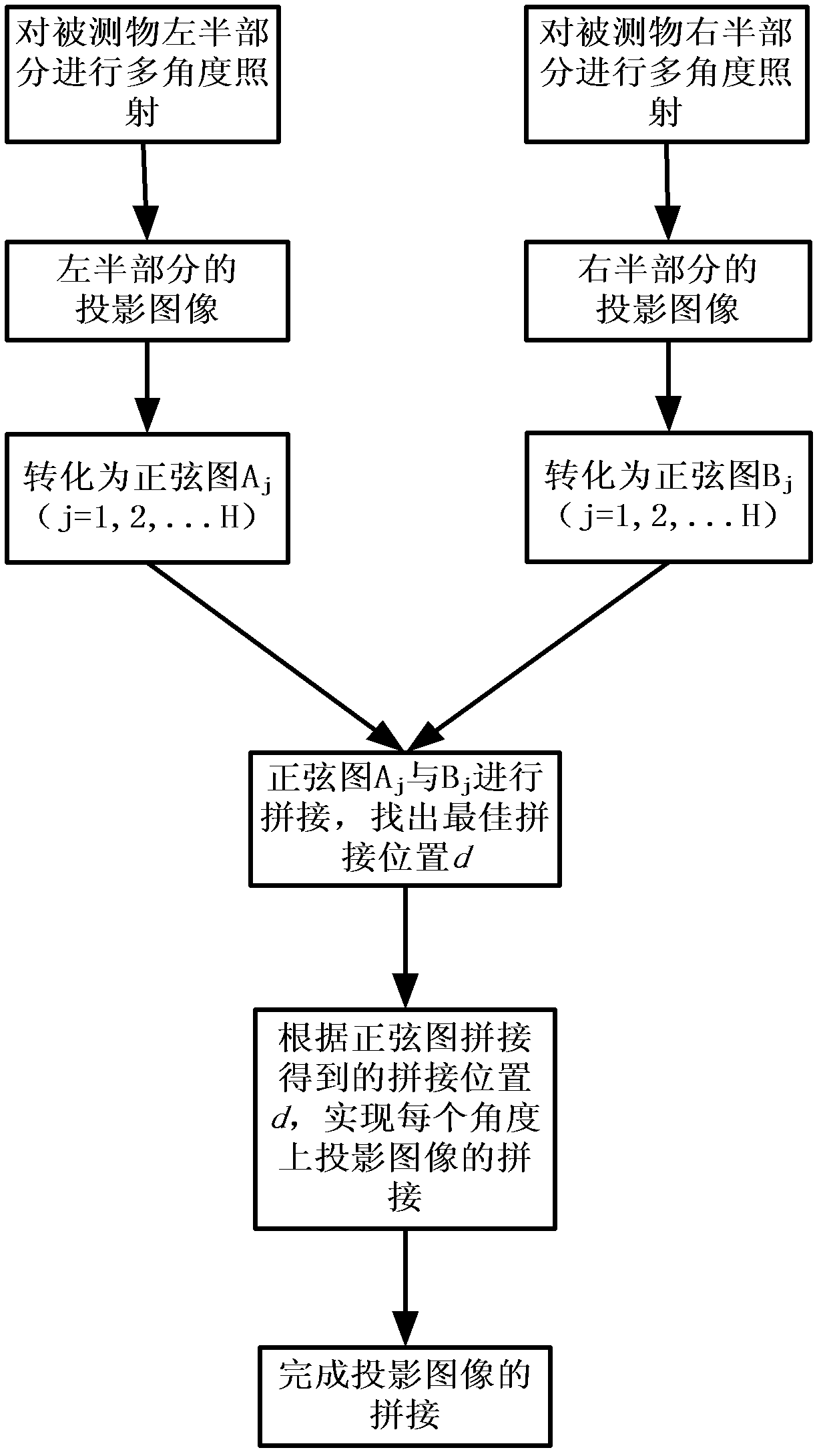
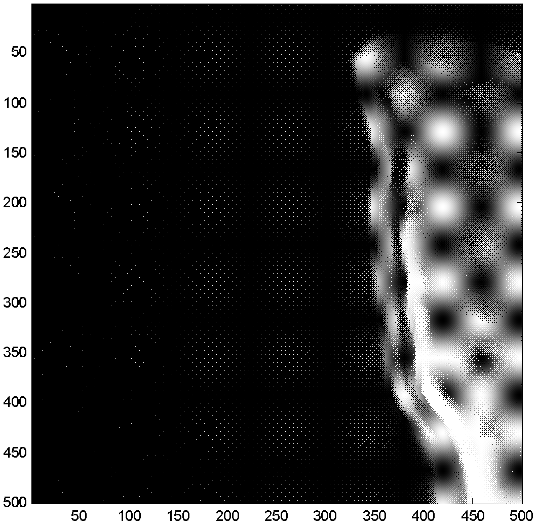
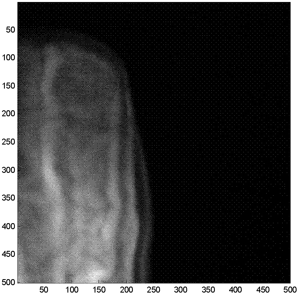
The invention discloses a measured object image splicing method based on an optical projection tomographic imaging system, which mainly solves the problem of blurring spliced regional images or obvious splicing mark in splicing a measured object image based on the optical projection tomographic imaging system in the prior art is solved. The measured object image splicing method based on the optical projection tomographic imaging system is realized by the following steps of: (1) respectively irradiating the left half part and the right half part of a measured object, and collecting to obtain projection images of the left half part and the right half part of the measured object; (2) respectively converting the left half part and the right half part of the measured object into a sinogram with a clear textural feature; (3) splicing the sinograms and confirming the splicing distance between the projection images by utilizing the correlation of image overlapping regions; and (4) finishing the splicing the projection images in a ramp function weighting way. The measured object image splicing method based on the optical projection tomographic imaging system has the advantages of high definition of spliced regions, small splicing marks and small calculated amount and can be used for carrying out three-dimensional reconstruction on the measured object.

Description

technical field [0001] The invention belongs to the technical field of image processing, and relates to image mosaic of an optical projection computer tomography system, and is especially suitable for image mosaic of an optical projection tomography system of parallel light beams. Background technique [0002] Optical projection tomography (OPT) is a new type of optical molecular imaging technology, and its imaging principle is similar to that of X-ray computed tomography. OPT uses visible light as the irradiation source, and is very suitable for imaging transparent or translucent samples in the range of 1-10mm, such as small animal embryos, organs, fruit flies, and nematodes. OPT can obtain structural imaging of the small intestine of small animals, and can also use fluorescent dyes or fluorescent proteins for molecular specific labeling to realize molecular characteristic imaging, so as to provide information for the functional positioning of disease-related genes, the mec...

Claims


Application Information

Patent Timeline
Patent Type & Authority Applications(China)
IPC IPC(8): G06T11/00G01N21/84
Inventor 朱守平鞠金采梁继民屈晓超陈多芳赵恒李军陈雪利侯彦宾田捷
Owner XIDIAN UNIV
Learn More