Chip turning device for surface-mounted device (SMD) light-emitting diode (LED) patch light splitting machine

A technology of steering device and spectrometer, which is applied in the direction of electrical components, circuits, semiconductor devices, etc., can solve the problems of low chip transmission efficiency, difficulty in breaking through the overall speed of equipment, and small chip ratio

Inactive Publication Date: 2012-01-18
广东志成华科光电设备有限公司
View PDF4 Cites 2 Cited by
  • Summary
  • Abstract
  • Description
  • Claims
  • Application Information

AI Technical Summary

Problems solved by technology

[0006] The current problem is: because the appearance of the chip is a symmetrical structure, when the vibrating plate is fed, the arranged chips may have two directions, but because the arrangement of the probes is unique, it is required that the direction of the chip is also unique during testing. of
However, the biggest problem with this method is that the chip transport efficiency is low and the speed is slow, and as a cuboid chip, there are more than a dozen postures on the vibrating track, and only one posture meets the requirements, and, for Ensure that chips that do not meet the requirements must not enter the final output track. The principle of air blowing is "rather lack than excess", that is to say, no missed judgments will occur, so misjudgments will occur, and the chips that were originally in the correct position will also be blown off the track. The proportion of chips that can enter the output track is too small, so the overall speed of the device is difficult to break through

Method used


Image

  • Chip turning device for surface-mounted device (SMD) light-emitting diode (LED) patch light splitting machine
  • Chip turning device for surface-mounted device (SMD) light-emitting diode (LED) patch light splitting machine
  • Chip turning device for surface-mounted device (SMD) light-emitting diode (LED) patch light splitting machine

Examples


Embodiment Construction

[0037] The present invention is further described in conjunction with the following examples.

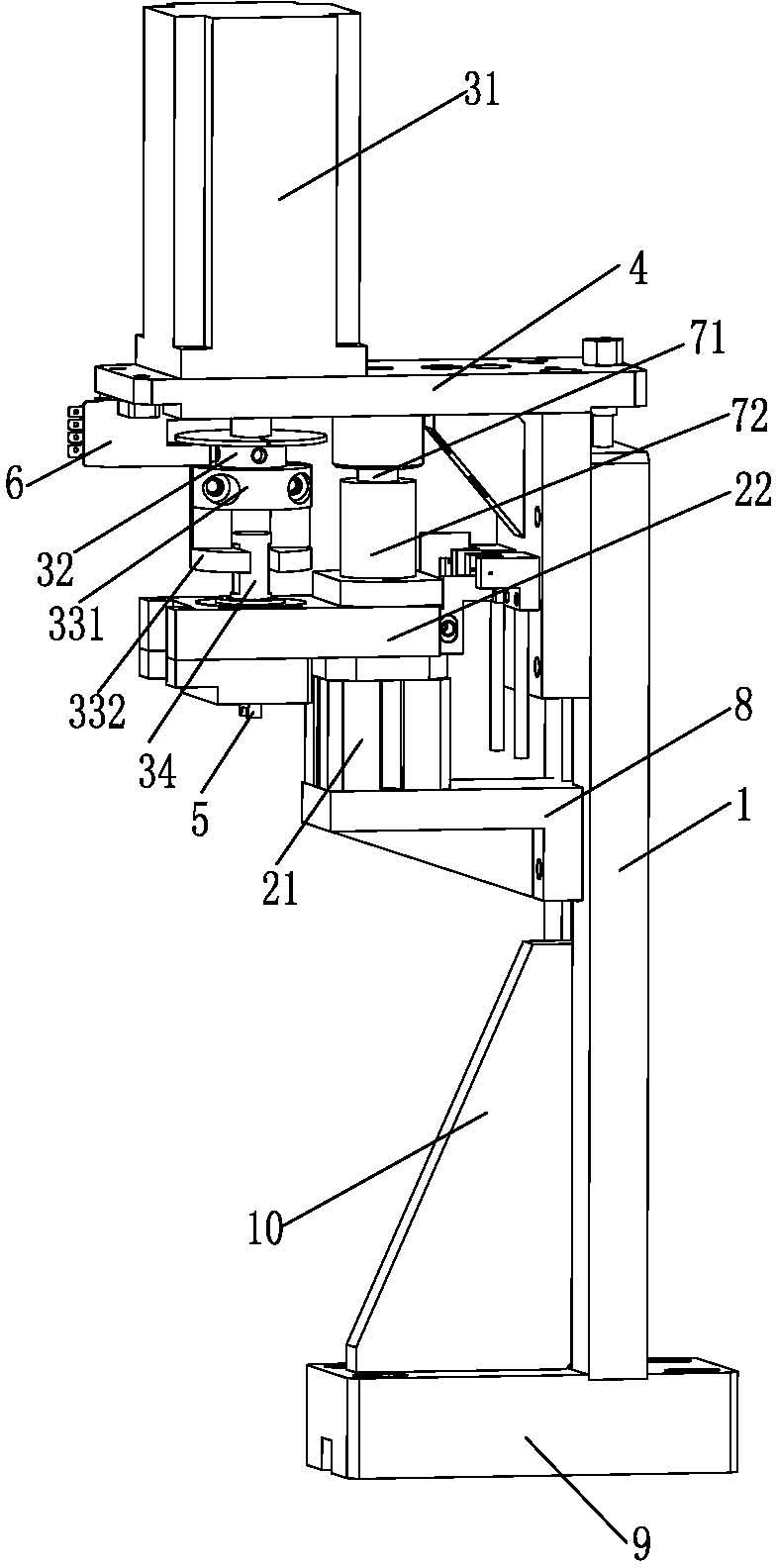
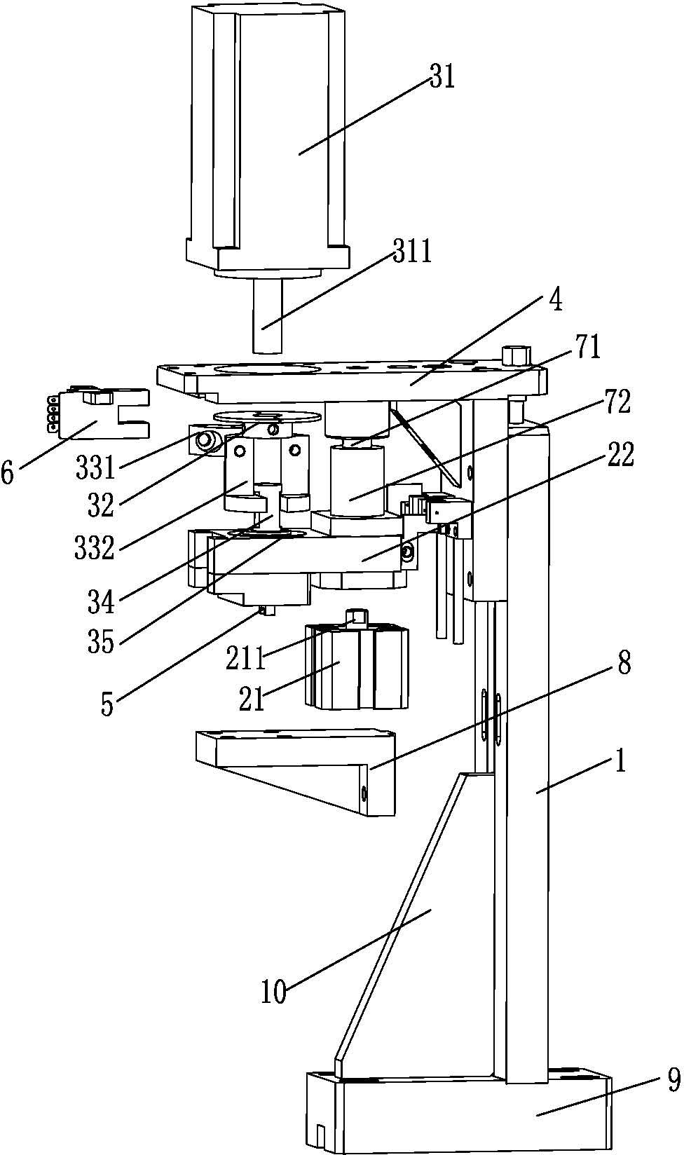
[0038] A specific embodiment of the chip steering device for a SMD LED patch spectrometer of the present invention, as figure 1 and figure 2 As shown, it includes a support plate 1 and a lifting mechanism, a steering mechanism, a chip suction device and a detection device 6 arranged on the support plate 1. The lifting mechanism includes a cylinder 21 and a lifting platform 22. The piston rod 211 of the cylinder 21 and the lifting platform 22 Connection; the steering structure includes a motor 31, an angle turntable 32, a coupling and a rotating shaft 34, the motor 31 is fixedly connected with the support plate 1 through the motor fixing plate 4, and the output shaft 311 of the motor 31 passes through the angle turntable 32 and is connected with the coupling One end of the coupling is connected, the other end of the coupling is connected with one end of the rotating shaft 34, the o...


PUM


Abstract

The invention relates to a chip turning device for a surface-mounted device (SMD) light-emitting diode (LED) patch light splitting machine, comprising a support plate, and a lifting mechanism, a turning mechanism, a chip absorbing device and a detection device which are arranged on the support plate; the lifting mechanism comprises a cylinder and a lifting platform; a piston rod of the cylinder is connected with the lifting platform; the turning mechanism comprises an electric motor, an angle turntable, a coupler and a rotating shaft; the electric motor is fixedly connected with the support plate through an electric motor fixing plate; an output shaft of the electric motor passes through the angle turntable and is connected with one end of the coupler; the other end of the coupler is matched and connected with one end of the rotating shaft; the other end of the rotating shaft passes through the lifting platform and is provided with the chip absorbing device; and the detection device is arranged at the front part of the chip turning device of the SME LED patch light splitting machine. The invention is the special chip turning device which is used for rotating a chip of which an electrode direction needs to be changed for 180 degrees, and has the characteristics of high separation speed, high test efficiency, simple structure and simplicity in operation.

Description

technical field [0001] The invention relates to the technical field of LED spectrometers, in particular to a chip steering device for an SMD LED patch spectrometer. Background technique [0002] SMD LED is a new type of surface-mounted semiconductor light-emitting device, which has the advantages of small size, large scattering angle, good uniformity of light emission, and high reliability. The light-emitting colors include various colors including white light. Therefore, it is widely used in various electronic products such as display screens, LCD panel backlights, decorative lighting, and general lighting. [0003] Because the LED packaging must be processed by color separation and light separation before leaving the factory, the LEDs are divided into many bins and categories according to parameters such as wavelength, brightness and operating voltage, and then the LEDs are automatically divided into different Bin tubes according to the set test standards. [0004] LED sp...

Claims


Application Information

Patent Timeline
IPC IPC(8): H01L33/00
Inventor 吴涛李斌秦小平
Owner 广东志成华科光电设备有限公司
Why Eureka
Try Eureka