Minute particle analyzing device and method

An analysis device and analysis method technology, which is applied in individual particle analysis, particle and sedimentation analysis, and material analysis, etc., can solve the problems of detection signal change, lower device performance stability and measurement accuracy, etc., and achieve position deviation suppression and stable measurement performance effect

Inactive Publication Date: 2012-01-25
SONY CORP +1
View PDF10 Cites 3 Cited by
  • Summary
  • Abstract
  • Description
  • Claims
  • Application Information

AI Technical Summary

Problems solved by technology

Therefore, the existing particle analysis device has the problem that the detection signal is significantly changed due to the positional deviation of the light spot on the sample flow, thereby degrading the stability of the performance of the device and the measurement accuracy.

Method used


Image

  • Minute particle analyzing device and method
  • Minute particle analyzing device and method
  • Minute particle analyzing device and method

Examples


Embodiment Construction

[0039] Embodiments will now be described with reference to the drawings.

[0040] 1. The particle analysis device according to the first embodiment

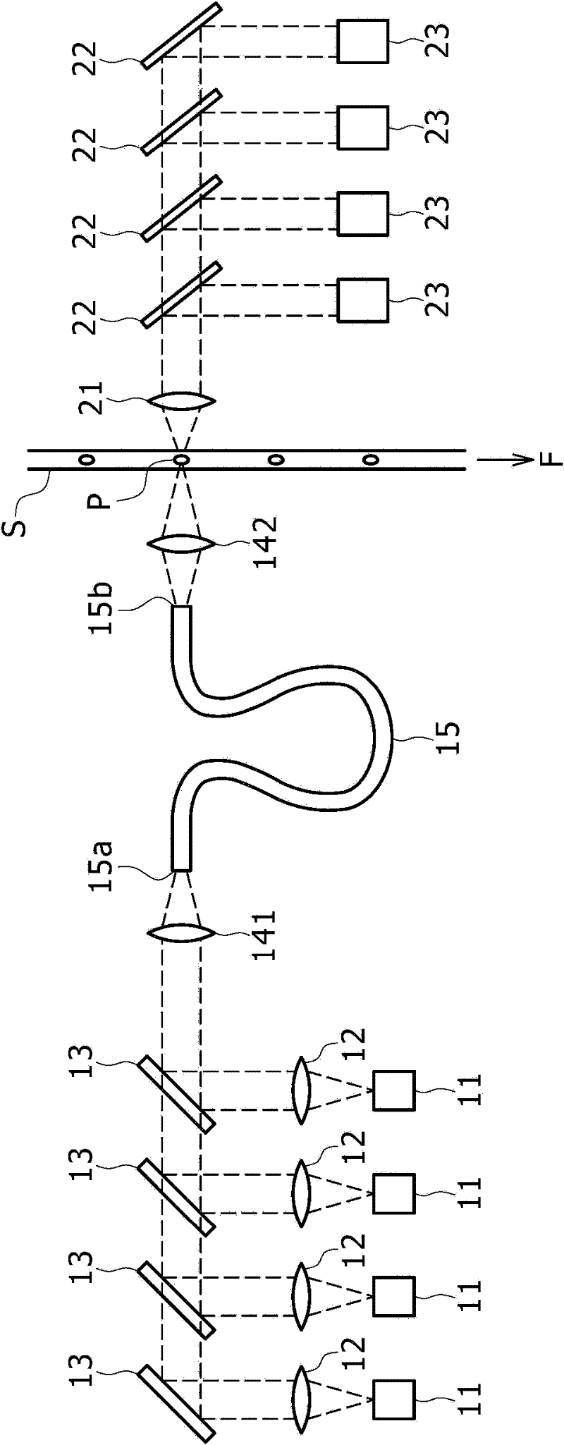
[0041] figure 1 is a schematic diagram showing a light application path and a light detection path in the microparticle analysis device according to the first embodiment.

[0042] refer to figure 1 , through a plurality of collimating lenses 12, the light beams (laser light) emitted from a plurality of light sources 11 are respectively parallelized, and the resulting parallel light beams from the collimating lenses 12 are respectively reflected on a plurality of reflectors 13 to follow the common The optical axis propagates. The resulting light beams propagating along the common optical axis are converged by the condenser lens 141 to enter the first end 15 a of the multimode optical fiber 15 .

[0043] The laser light incident on the first end 15 a of the multimode fiber 15 propagates in the multimode fiber 15 to be emitted f...


PUM

PropertyMeasurementUnit
sizeaaaaaaaaaa

Abstract

A minute particle analyzing device includes: a light source; a first condenser lens for condensing light from the light source to a first end of a multimode optical fiber; a second condenser lens for condensing the light emerging from a second end of the multimode optical fiber to a minute particle; and a detector for detecting light generated from the minute particle by the application of the light from the light source.

Description

technical field [0001] The present invention relates to a microparticle analysis device and method, and more particularly, to a microparticle analysis device for optically analyzing properties of microparticles such as cells and microbeads. Background technique [0002] A particle analysis device applies light to particles flowing in a channel (formed in a flow cell or on a microchip) and detects scattered light from each particle or fluorescence from each particle itself or labeled on each particle Fluorescence produced by a substance, whereby the optical properties of each particle are measured. The microparticle analysis device further performs sorting of a population from the microparticles, wherein the population is determined to satisfy a predetermined condition based on the measurement result of the optical characteristic. Specifically, such a device for measuring optical properties of cells (as microparticles) or sorting a population of cells satisfying predetermine...

Claims


Application Information

Patent Timeline
Patent Type & Authority Applications(China)
IPC IPC(8): G01N15/14
CPCG01N15/1434G01N21/53G01J3/1256G01J3/024G01N15/1459G01N21/645G02B6/14G02B6/32G02B6/4215
Inventor 浩司高崎濑尾胜弘外石满晋司山田福本敦加里·杜拉克
Owner SONY CORP
Why Eureka
Try Eureka