Flue gas latent energy recovery method in glass smelting kiln

A technology of glass melting furnace and recycling method, which is applied in glass production, glass furnace equipment, glass manufacturing equipment, etc., can solve the problems of easy pollution of batch materials and low comprehensive utilization rate, shorten the time span, reduce smoke and dust emissions, The effect of reducing production costs

Active Publication Date: 2012-02-01
(CNBM) BENGBU DESIGN & RES INST FOR GLASS IND CO LTD
View PDF3 Cites 8 Cited by
  • Summary
  • Abstract
  • Description
  • Claims
  • Application Information

AI Technical Summary

Problems solved by technology

[0004] The purpose of the present invention is to overcome the defects of low comprehensive utilization rate and easy pollution of batch materials in the prior art, and propose a method for recovering the potential of flue gas from an all-oxygen glass melting furnace and a potential recovery device

Method used


Image

  • Flue gas latent energy recovery method in glass smelting kiln
  • Flue gas latent energy recovery method in glass smelting kiln
  • Flue gas latent energy recovery method in glass smelting kiln

Examples


Embodiment 1

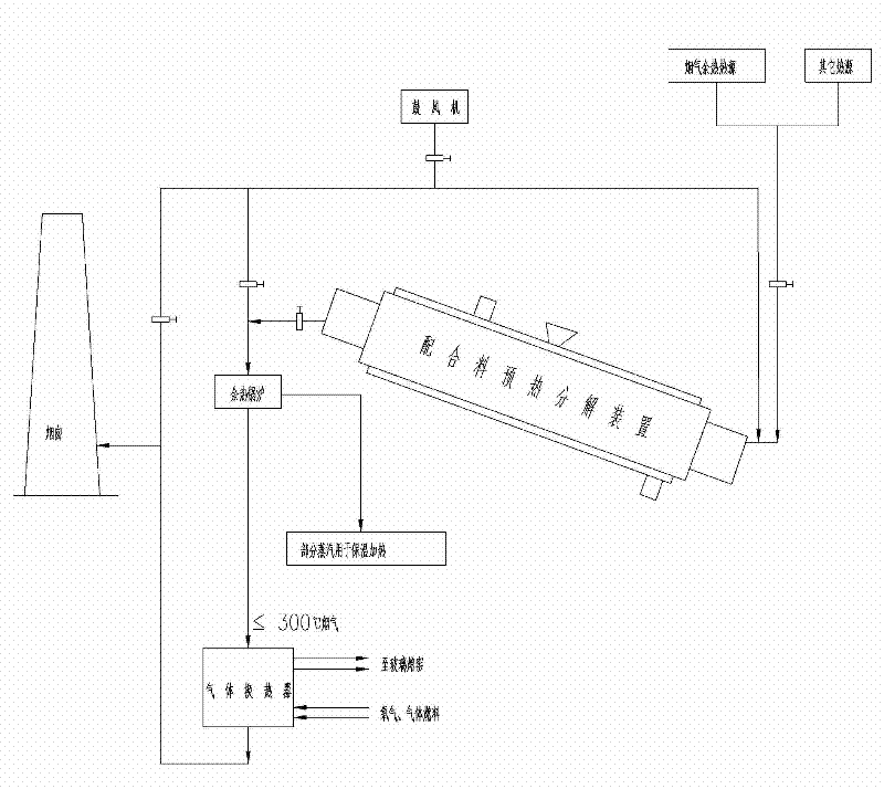
[0058] Such as figure 1 As shown, the system composition adopted in a kind of glass melting kiln flue gas potential recovery method provided by the present invention is as follows:

[0059] The high-temperature flue gas and other heat sources of the glass melting furnace are introduced into the inlet end of the batch material preheating decomposition device through the pipeline, the outlet end of the batch material preheating decomposition device is connected to the waste heat boiler through the pipeline, and the outlet end of the waste heat boiler is connected to the gas heat exchanger through the pipeline. The outlet end of the gas heat exchanger is connected to the chimney through a pipe.

[0060] In addition, a blower is provided to guide the low-temperature air to the inlet and outlet of the preheating and decomposing device for the batch material through the pipeline, so as to adjust the temperature entering the preheating and decomposing device for the batch material. ...

Embodiment 2

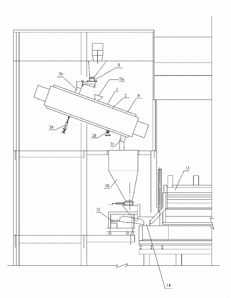
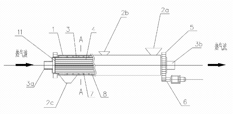
[0067] Such as figure 2 As shown, it is a batch material preheating and decomposition device provided by the present invention—a grid type heat pipe fluidized bed and a structural diagram of a melting furnace system, which includes a batch material vibrating feeder 1 above the melting furnace frame, a melting furnace frame below The thermal insulation feeder 3 and the sealing feeder 4, the sealing feeder 4 will batch the material into the feeding port 5 of the melting furnace 6, and these all belong to the prior art.

[0068] A group of grid-shaped heat pipe fluidized beds 2 are set in the furnace frame, and the upper and lower parts of each decomposition fluidized bed 2 outside the kiln are respectively provided with a feed port 2a, an exhaust port 2b and a discharge port 2c, which are respectively connected with the vibrating feeder 1 cooperates with sealing feeder 4. The lower part of the grid-shaped heat pipe fluidized bed 2 is provided with a hinge shaft 2d to cooperate...

Embodiment 3

[0072] Such as Figure 6 Shown is another kind of batch material preheating decomposition device provided by the present invention—the structural schematic diagram of the heat pipe fluidized bed device, which includes the following two parts:

[0073] a. A heat pipe heat exchanger, which includes an outer thermal insulation shell 100, a group of high-temperature heat pipes 200 are arranged in the shell, and a partition plate 300 is set in the shell to separate the inner cavity of the shell into a heat collecting area 100a and a heat releasing area 100b . A blower 400 is arranged outside the housing, which is connected to one side of the heat release area 100b through an air inlet pipe 600a, and the other side of the heat release area is connected to an air outlet pipe 600b. As shown in the figure, valves are provided in the air inlet pipe 600a and the air outlet pipe 600b. The high-temperature flue gas inlet pipe 500a is connected to one side of the heat collection area 100a...


PUM


Abstract

The invention relates to a high-temperature flue gas latent energy recovery method in a glass smelting kiln, comprising the following three stages of: 1, regulating the high-temperature flue gas led out from the glass smelting kiln to 800-1000 DEG C, conveying the regulated flue gas into a batch preheating and decomposing device to preheat and decompose the batch at outside of the kiln, and heating up the batch from room temperature to 280-608 DEG C; 2, introducing the flue gas, which is not more than 608 DEG C and is processed in the batch preheating and decomposing device, into an exhaust-heat boiler; 3, introducing the flue gas, which is not more than 300 DEG C and is processed in the exhaust-heat boiler, into a gas heat exchanger, and heating the combustion-supporting gas. With the method, energy consumption of glass smelting is reduced, energy is saved, and dust emission is reduced; fuel and combustion-supporting oxygen can be further saved by not less than 20%; thermal energy of the flue gas is recovered fully; and the batch preheating and decomposing device can shorten a pre-smelting section of the smelting kiln and reduce investment on the kiln.

Description

technical field [0001] The invention relates to a method and a device for recovering the potential energy of high-temperature flue gas in a glass melting kiln, in particular to a method for recovering the potential energy of flue gas and a device for recovering the potential energy in a glass full-oxygen combustion melting process. Background technique [0002] The use of oxy-fuel combustion in the glass industry has been recognized as the best low-carbon process option for the glass melting process. How to balance the reduction (fuel consumption) and increase (oxygen production energy consumption) after implementing the oxy-fuel combustion process? Reducing operating costs, realizing energy conservation and emission reduction - has become a top priority. [0003] After the oxy-fuel combustion process has successfully replaced the traditional glass melting process, the potential of recovering high-temperature flue gas from oxy-fuel combustion has become a key topic in the pr...

Claims


Application Information

Patent Timeline
Patent Type & Authority Applications(China)
IPC IPC(8): C03B5/237
CPCY02P40/50
Inventor 彭寿徐嘉麟王芸彭程张仰平杨培广曹艳平王友乐杨扬方亮葛莹莹钱学君
Owner (CNBM) BENGBU DESIGN & RES INST FOR GLASS IND CO LTD
Why Eureka
Try Eureka