Method for manufacturing ultrahigh-frequency radio frequency identification (RFID) tag

A technology of RFID tags and manufacturing methods, applied in the field of radio frequency identification technology (RFID), can solve problems such as high manufacturing costs, environmental pollution, and many processes, and achieve the effects of reducing manufacturing costs, simplifying manufacturing processes, and avoiding pollution

Inactive Publication Date: 2012-02-01
WUXI BANGPU JIUSHUN MICROELECTRONICS
View PDF3 Cites 16 Cited by
  • Summary
  • Abstract
  • Description
  • Claims
  • Application Information

AI Technical Summary

Problems solved by technology

[0006] (1) There are many processes and the manufacturing cost is high;
[0007] ⑵Wastewater produced in the manufacturing process will cause certain pollution to the environment

Method used


Image

  • Method for manufacturing ultrahigh-frequency radio frequency identification (RFID) tag
  • Method for manufacturing ultrahigh-frequency radio frequency identification (RFID) tag
  • Method for manufacturing ultrahigh-frequency radio frequency identification (RFID) tag

Examples


Embodiment 1

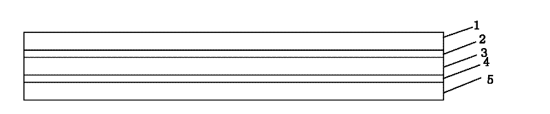
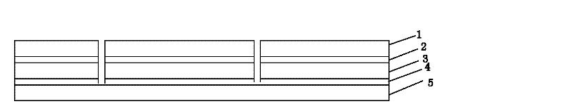
[0046] like figure 1 , figure 2As shown, the UHF RFID antenna is die-cut on the multi-layer structural material with a knife die. The multi-layer structure material is composed of Mylar metal foil layer, self-adhesive layer and release layer. The Mylar metal foil layer can be divided into three layers: conductive layer, adhesive layer and reinforcement layer, and its thickness is not more than 60μm. The release layer is the bottom layer, the self-adhesive layer is on the top of the release layer, the Mylar metal foil layer is on the top of the self-adhesive layer, and the conductive layer is on the top of the Mylar metal foil layer. The adhesive layer connects the conductive layer and the conductive layer. The layers are glued together. The self-adhesive layer is medium-strength or low-strength self-adhesive, located below the Mylar metal foil layer, the coating thickness is not greater than 15μm, the release layer is white silicon paper, cardboard, PVC, PET, PP, located T...

Embodiment 2

[0048] The mechanical knife mold in the first embodiment can also be replaced by a laser with a medium and small power laser source. Half-cut through the layer structure material, even with laser cutting, cut through the Mylar metal foil layer through laser focusing and adjusting laser power, stop at the self-adhesive layer, and the release layer is completely preserved; it can also be fully cut through, even with laser cutting It can penetrate all the film layers; it can also partially cut through, that is, half cut through at the selected position.

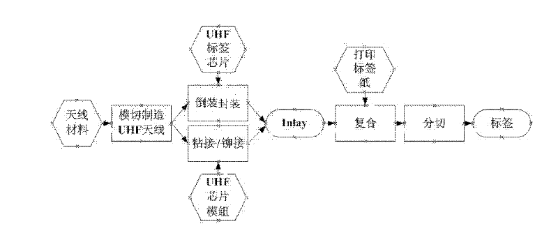
[0049] In summary, the technical solution of the present invention adopts the die-cutting method to die-cut the UHF RFID antenna. Compared with the etching method, a large amount of acid and alkali chemicals are no longer used, and the pollution to the environment is avoided. The simplification of the manufacturing process reduces the manufacturing cost of the UHF RFID antenna, thereby reducing the manufacturing cost of the UHF ...


PUM


Abstract

The invention discloses a method for manufacturing an ultrahigh-frequency radio frequency identification (RFID) tag. The method comprises the following steps of: cutting an ultrahigh-frequency RFID antenna on a multilayer structural material by using a knife die; inversely encapsulating an ultrahigh-frequency RFID chip in the terminal of the ultrahigh-frequency antenna or encapsulating the ultrahigh-frequency RFID chip into a chip module and assembling the chip module to the terminal of the ultrahigh-frequency RFID antenna by sticking or riveting to form an inlay; sticking a piece of printing face paper for marking tag information to the inlay; and cutting the inlay stuck with the printing face paper. Compared with an etching method, the method has the advantages that: because the ultrahigh-frequency RFID antenna is cut by adopting a knife die forming method, massive acid and alkali chemicals are not used, and environmental pollution is avoided. By simplifying the manufacturing process, the manufacturing cost of the ultrahigh-frequency RFID antenna is reduced, so that the manufacturing cost of the ultrahigh-frequency RFID tag is reduced, and the ultrahigh-frequency RFID tag can be widely applied.

Description

technical field [0001] The invention relates to the field of radio frequency identification technology (RFID), in particular to a manufacturing method of an ultra-high frequency RFID tag. Background technique [0002] At present, as an important application of Internet of Things technology, radio frequency identification technology (RFID) has developed rapidly in recent years. Compared with other item management systems, such as bar code systems, radio frequency identification (RFID) has irreplaceable advantages: first, it can identify non-specific single items, so that it is not necessary to identify only one type of item like bar codes; second, it uses wireless Radio frequency technology can be read without contact; third, it can read multiple items at the same time, and is widely used in logistics, warehousing and other fields to obtain item information accurately and quickly, so as to realize efficient and quick management and scheduling of items. As the transponder in ...

Claims


Application Information

Patent Timeline
Patent Type & Authority Applications(China)
IPC IPC(8): G06K19/077
Inventor 龚挺安兵
Owner WUXI BANGPU JIUSHUN MICROELECTRONICS
Why Eureka
Try Eureka