Patterned graphene field emission cathode and preparation method thereof

An emission cathode, patterning technology, applied in cold cathode manufacturing, electrode system manufacturing, discharge tube/lamp manufacturing, etc. problem, to achieve the effect of low cost, high electron emission current density and low production cost

Active Publication Date: 2012-02-01
FUZHOU UNIV
View PDF2 Cites 9 Cited by
  • Summary
  • Abstract
  • Description
  • Claims
  • Application Information

AI Technical Summary

Problems solved by technology

However, this method cannot realize the image preparation of graphene cathode; due to the low softening temperature of polystyrene and easy decomposition, the high temperature (local temperature up to 1000 °C) generated during the field emission process o C) Polystyrene can be decomposed; at the same time, due to the use of polystyrene, the existing high-temperature vacuum sealing process cannot be used (the peak sealing temperature is 450 o C) Preparation of field emission devices

Method used


Image

  • Patterned graphene field emission cathode and preparation method thereof
  • Patterned graphene field emission cathode and preparation method thereof
  • Patterned graphene field emission cathode and preparation method thereof

Examples


Embodiment 1

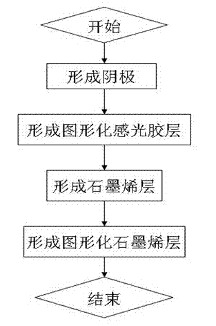
[0029] The preparation process of a patterned graphene field emission cathode is as follows:

[0030] Step 1: Preparation of zinc oxide precursor sol

[0031] Accurately weigh 8.2621g of zinc acetate dihydrate with an electronic balance, and put it into a conical flask filled with about 30mL of isopropanol solvent. Stir with a constant temperature magnetic stirrer and keep the temperature at 70 o C, after 10 minutes, put 4.6mL of ethanolamine stabilizer and stir for 10 minutes. After cooling, titrate with isopropanol in a 50mL volumetric flask. Finally at 70 o After stirring on a constant temperature magnetic stirrer at C for 1 hour, a uniform and transparent sol was formed. After standing still for at least 48 hours, a zinc oxide precursor sol solution is formed.

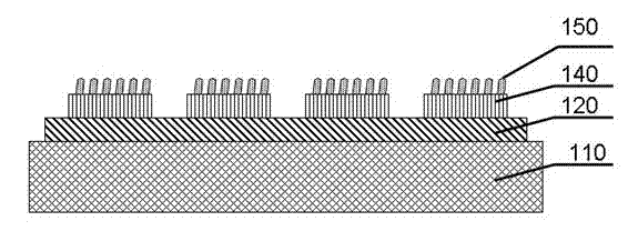
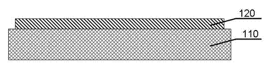
[0032] Step 2: preparation of the glass substrate 110 . Carry out scribing and cleaning on the substrate material of the glass substrate 110 .

[0033] Step 3: Preparation of cathode 120 . Electrode 120 is ...

Embodiment 2

[0044] The preparation process of a patterned graphene field electron emission cathode is the same as that of Embodiment 1, except that the conductive adhesion layer 130 is made of indium oxide doped with tin (ITO). Its step 2, step 3, step 4, step 5, step 6 are identical with embodiment 1, and the preparation of step 1 sol precursor is as follows:

[0045] Weigh a certain amount of indium nitrate pentahydrate crystals, dissolve in acetylacetone, reflux at 60°C for 3 hours, mix tin chloride pentahydrate dissolved in a small amount of absolute alcohol with it (the molar ratio of tin and indium is 1:10 ), to obtain ITO sol.

[0046] The present invention provides a patterned graphene field electron emission cathode, the conductive adhesion layer can be but not limited to zinc oxide film, ITO film, tin oxide film, silicon film, titanium oxide film.

[0047] The invention proposes a patterned graphene field electron emission cathode. Through the introduction of the inorganic con...


PUM

PropertyMeasurementUnit
electron mobilityaaaaaaaaaa

Abstract

The invention discloses a patterned graphene field emission cathode and a preparation method thereof. The patterned graphene field emission cathode comprises a cathode substrate, a cathode arranged on the surface of the cathode substrate and a graphene layer arranged on the surface of the cathode, wherein a conductive adhesion layer is introduced between the cathode and the graphite, and the patterned preparation of the graphene layer is realized through a photoetching-stripping technology, and therefore the patterned field emission cathode is obtained. The graphene field emission cathode disclosed by the invention has the advantages of high emission current density, simple technological process, low cost and emission stability and uniformity, realizes patterned preparation and is suitable for a field emission display, a field emission flat light source, a field emission backlight source for a liquid crystal display and a cold cathode of a vacuum electronic device.

Description

technical field [0001] The invention belongs to the technical field of vacuum electronics, and specifically relates to a patterned graphene field electron emission cathode, which is suitable for making field emission cathodes in field emission flat panel displays (FEDs) and cold cathodes for vacuum electronic devices. Background technique [0002] Field emission display device is a new type of flat panel display technology. Field emission display technology is an extension of cathode ray tube (CRT) technology. It has the advantages of wide viewing angle, bright colors and fast response speed of CRT display. In the current Among all kinds of flat panel displays, only FED can achieve the image display quality of traditional CRT, and at the same time, it has the advantages of thinness and lightness such as liquid crystal display (LCD). The core component of the FED display is the field emission cold cathode array, in which the cathode material determines the performance of the ...

Claims


Application Information

Patent Timeline
Patent Type & Authority Applications(China)
IPC IPC(8): H01J29/04H01J9/02
Inventor 李福山郭太良吴朝兴张永志张蓓蓓寇丽杰
Owner FUZHOU UNIV
Why Eureka
Try Eureka