Magnetic steel used for permanent-magnet direct drive wind power generator

A wind turbine, permanent magnet direct drive technology, applied in the field of magnetic steel, can solve the problems of large centrifugal force, large pulsation loss, complex claw pole structure, etc., to prevent falling off and oxidation, strong mechanical structure strength, and low precision requirements. Effect

Inactive Publication Date: 2012-02-01
SHANGHAI WANDE WIND POWER
View PDF5 Cites 1 Cited by
  • Summary
  • Abstract
  • Description
  • Claims
  • Application Information

AI Technical Summary

Problems solved by technology

The structure of the hybrid rotor is complicated, and the processing accuracy of the rotor groove and permanent magnet is high, and the manufacturing is time-consuming
[0013] The representative structure of the axial rotor is the claw pole rotor, which has the advantages of simple shape, good magnetic properties, uniform magnetization, and high utilization rate of the permanent magnets. Due to the large centrifugal force, special fastening measures are required. The claw poles and flanges account for a large proportion of the rotor volume, and the mass of the motor increases. It is not suitable to be made into a power frequency generator. The pulsation loss in the claw poles is large and the efficiency decreases.

Method used


Image

  • Magnetic steel used for permanent-magnet direct drive wind power generator
  • Magnetic steel used for permanent-magnet direct drive wind power generator
  • Magnetic steel used for permanent-magnet direct drive wind power generator

Examples


Embodiment

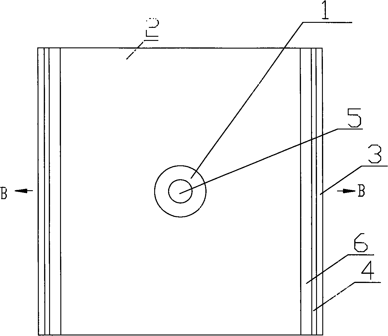
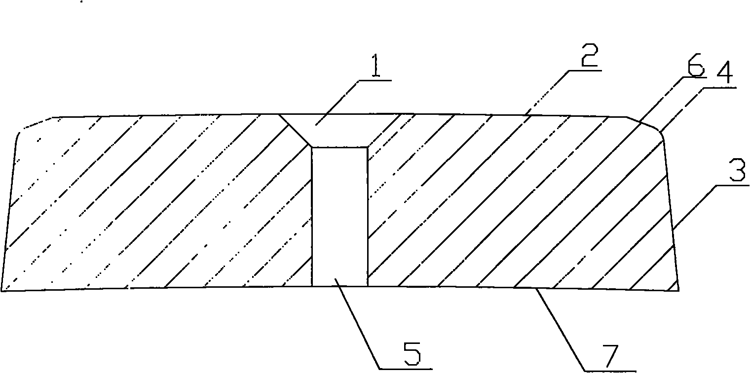
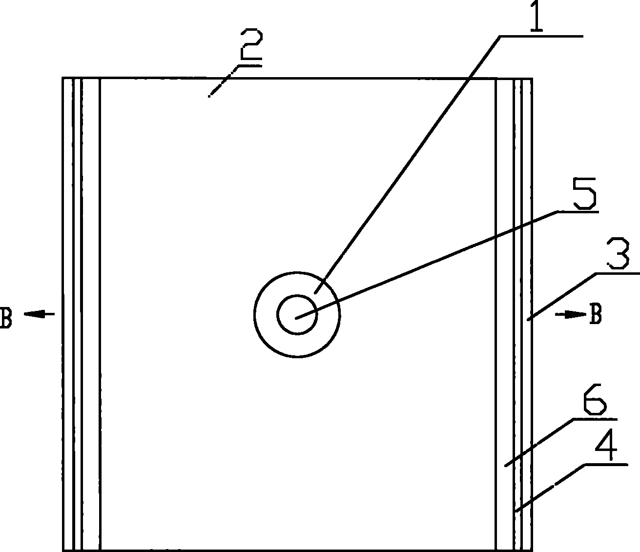
[0033] Such as figure 1 , figure 2 As shown, a magnet for permanent magnet direct-drive wind power generators, the magnet has a rectangular cross section with a through hole in the center, its upper surface 2 is arched, the lower surface 7 is arched, and the sides include 6 on the upper side, 4 on the middle side and 3 on the lower side. The through hole includes an upper part 1 and a lower part 5, wherein the upper part 1 is a rounded frustum, and the lower part 5 is a cylinder. The arched arcs of the upper surface 2 and the lower surface 7 have the same diameter. The upper side 6 is rectangular. The middle side 4 is arched. The lower side 3 is rectangular.

[0034] There is a through hole at the center of the magnetic steel that can be fixed with a countersunk screw, and it is viewed as a rectangle from above and below. The bottom surface has the same arc as the rotor outer circle radius, and the side is arc-shaped. The surface of the magnetic steel is galvanized.

[...


PUM


Abstract

The invention relates to magnetic steel used for a permanent-magnet direct drive wind power generator. A transverse section of the magnetic steel is in a shape of a rectangle. A through hole is arranged in a center of the transverse section. An upper surface and a lower surface are in a shape of an arc. Side surfaces comprise an upper side surface, a middle side surface and a lower side surface. Compared to the prior art, the magnetic steel of the invention possesses a simple structure, good manufacturability, low costs and the like.

Description

technical field [0001] The invention relates to a magnet for a generator, in particular to a magnet for a permanent magnet direct drive wind power generator. Background technique [0002] The structure of permanent magnet synchronous generator can be divided into two types: outer rotor and inner rotor. We know the relationship between air gap, diameter and motor capacity. Obviously, for motors with the same air gap and diameter, there is no difference in electrical performance between the outer rotor structure and the inner rotor structure. [0003] The magnet steel of the permanent magnet motor with the inner rotor is fixed on the outside or the outer surface of the rotor. If the permanent magnet of the permanent magnet motor with the inner rotor is fixed on the outer surface of the inner rotor, a compression ring is generally used outside the permanent magnet. Used to protect the magnet. Another method is to fasten the magnets in the dovetail slots on the specially proce...

Claims


Application Information

Patent Timeline
IPC IPC(8): H02K1/06H02K1/27
CPCH02K1/278H02K7/1838Y02E10/725Y02E10/72
Inventor 贾大江
Owner SHANGHAI WANDE WIND POWER
Why Eureka
Try Eureka