Combined type electric deduster

An electrostatic precipitator and combined technology, which is applied in the field of dust collection devices, can solve the problems of arcuate deformation of cathode wires, high cost of cathode insulating sleeves, difficulty in ensuring errors due to changes in the distance between anode plate frames and cathode wire frames, etc. The effect of pulling deformation

Inactive Publication Date: 2012-02-08
SHENYANG LONGDA ENVIRONMENTAL PROTECTION
View PDF6 Cites 14 Cited by
  • Summary
  • Abstract
  • Description
  • Claims
  • Application Information

AI Technical Summary

Problems solved by technology

[0036] 2. Since the anode plate frame and the cathode frame are large, the degree of deformation is large, the distance between the anode plate frame and the cathode wire frame is small, and the limitless device controls it, resulting in the distance between the anode plate frame and the cathode wire frame It is difficult to ensure that the error is within the allowable range!
[0037] 3. Because in the electrostatic precipitator, the anode plate frame and the cathode frame are independent systems, but the anode plate frame and the cathode frame are respectively crossed and combined to form a dust collection electric field. Since the anode plate frame and the cathode frame are respectively It is composed of multiple rows of common combinations. Since the cumulative tolerance correction of multi-row combinations is extremely difficult, it is even more difficult to ensure that the design tolerance of the pole spacing is up to standard!
[0038] 4. Due to the uneven distribution of gas in the electric field, the cross-section of the electric field is heated differently, resulting in uneven deformation of the electrode plate and the cathode wire frame, which will make the serious exceeding of the installation error of the distance between different poles more serious.
[0039] 5. The steel pipe used in the cathode wire frame, due to gravity, ...

Method used


Image

  • Combined type electric deduster
  • Combined type electric deduster
  • Combined type electric deduster

Examples


Embodiment Construction

[0072] In this example,

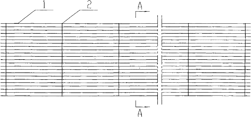
[0073] Such as figure 1 As shown, it is a transparent anode plate (3) made of U-shaped metal laths (1), arranged and combined at equal intervals, connected and fixed by positioning pins (2).

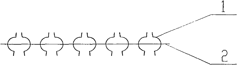
[0074] Such as figure 2 shown; is figure 1 In the embodiment 1 of the transparent anode plate in the present invention in A-A, U-shaped metal laths (1) are used, which are equally spaced, each of which is alternately arranged and combined with each other repeatedly, and is connected and fixed by positioning pins (2). Transverse sectional view of the through-type anode plate (3).

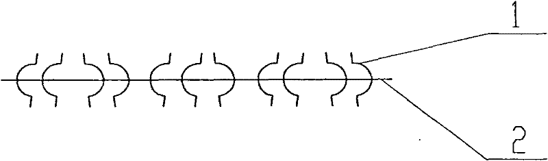
[0075] Such as image 3 shown; is figure 1 The second embodiment of the transparent anode plate in the present invention in A-A is made by using U-shaped metal laths (1), equidistant, every two alternately arranged and combined with each other, and connected and fixed by positioning pins (2) Transverse sectional view of the transparent anode plate (3).

[0076] Such as Figure...


PUM


Abstract

The existing electric deduster at home and abroad has the defects that a design structure is reasonable; faults are produced frequently; and especially, heteropole separation distance errors are difficult to be controlled in installation construction and thus the heteropole separation distance errors largely exceed the standard frequently so that applied secondary voltage is greatly insufficient and it is influenced that dedusting efficiency reaches the standard. Aiming at the defects, the invention provides a combined type electric deduster. The combined type electric deduster is a combined type dust collecting device. A corona discharging pole wire and an anode plate are assembled accurately outside a box body of the combined type electric deduster and then internal parts of the combined type electric deduster are installed. Therefore, assembling errors can be limited to a minimal value; an anode plate dust collecting area is greatly improved simultaneously; a complex cathode wire framework suspension installation system and a complex cathode rapping ash removal device are left out so that sources of faults produced frequently are eliminated; and smoke dust emission concentration of the combined type electric deduster is reduced a value of 1 to 0mg/Nm<3>. The technology of the combined type electric deduster is suitable for large, middle and small electric dedusters.

Description

technical field [0001] The present invention relates to a dust collecting device in an electric precipitator for removing industrial dust particles, in particular to a dust collecting device with a combined frame structure of a transparent anode plate and a corona discharge electrode line applied in an electric precipitator electric field device. Background technique [0002] As we all know, at present, all kinds of dust removal equipment technologies such as electrostatic precipitator and bag filter in the environmental protection dust removal industry at home and abroad have a dust concentration of tens of mg / Nm 3 None of the above can completely remove the aerosol soot particles below 0.2 microns in industrial smoke and dust. At least 10 million tons of micron-sized aerosol soot particles are discharged into the atmosphere every year in my country. However, it is these micron-sized aerosol soot particles that With the characteristic of being suspended in the air for a lon...

Claims


Application Information

Patent Timeline
IPC IPC(8): B03C3/09B03C3/47B03C3/86B03C3/76B03C3/66
CPCB03C3/86B03C3/09B03C3/08B03C3/82B03C3/025
Inventor 袁野
Owner SHENYANG LONGDA ENVIRONMENTAL PROTECTION
Why Eureka
Try Eureka