Hydrogenation method for catalytic cracking heavy cycle oil

A technology for catalytic cracking of heavy oil and catalysts, which is applied in the fields of hydroprocessing, petroleum industry, and hydrocarbon oil treatment. It can solve the problems of catalyst bed clogging, achieve the effects of improving cracking performance, efficient utilization, and reducing SOx emissions.

Active Publication Date: 2012-02-08
CHINA PETROLEUM & CHEM CORP +1
View PDF6 Cites 3 Cited by
  • Summary
  • Abstract
  • Description
  • Claims
  • Application Information

AI Technical Summary

Problems solved by technology

[0008] The purpose of the present invention is to propose a kind of catalytic cracking heavy oil hydrogenation method with protective reactor system on the basis of prior art, adopt this method to economically and effectively solve the problem of catalyst bed blockage of catalytic cracking heavy oil hydrogenation unit, Ensure the long-term stable operation of the hydrogenation unit

Method used


Image

  • Hydrogenation method for catalytic cracking heavy cycle oil
  • Hydrogenation method for catalytic cracking heavy cycle oil
  • Hydrogenation method for catalytic cracking heavy cycle oil

Examples


Embodiment 1

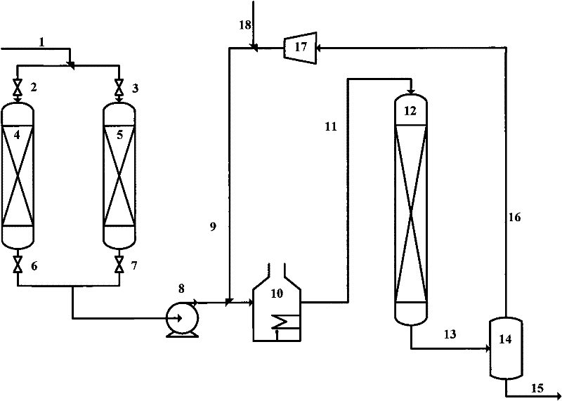
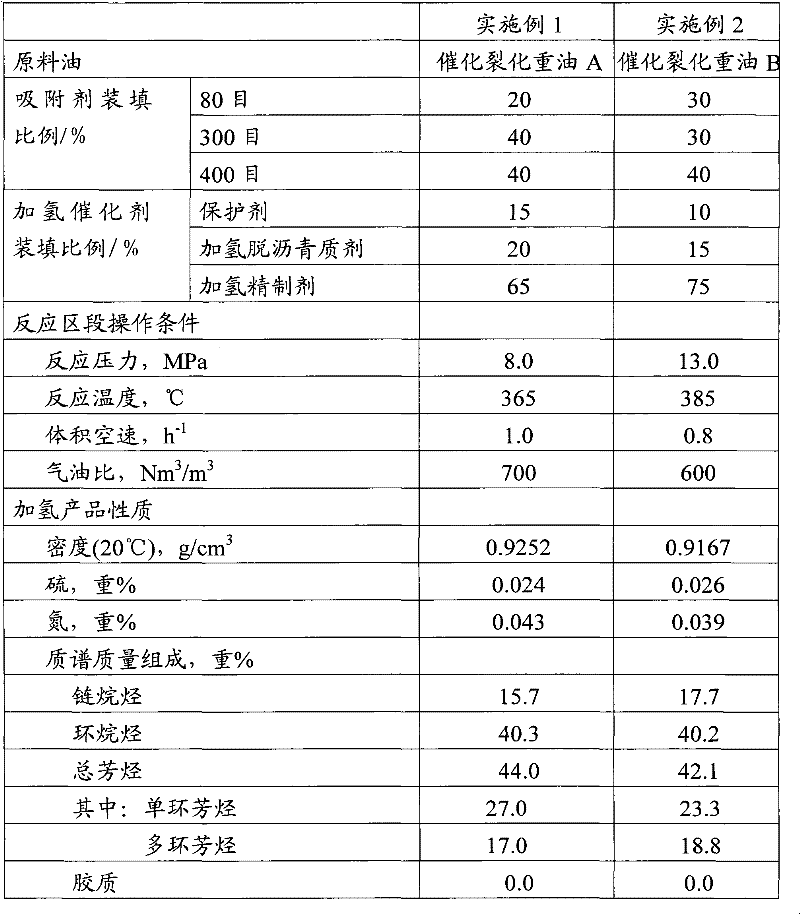
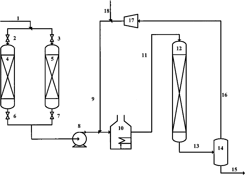
[0033] Catalytic cracking heavy oil A first passes through the protection reactor A, contacts with the adsorbent to filter out most of the catalytic cracking catalyst powder, is pressurized by the raw material oil pump and mixed with hydrogen, and then enters the heating furnace, and then enters the hydrogenation reactor after heating, which is followed by hydrogenation protection. agent, hydrodeasphalting agent, and hydrofining agent. The oil produced by hydrogenation is separated from gas and liquid by a high pressure separator, the liquid product is discharged from the device, and the gas is compressed by the compressor and mixed with new hydrogen and then mixed with the raw material oil. When the protection reactor A reaches the saturated adsorption capacity, blockage occurs, and the pressure difference rises, the protection reactor B is cut into the system, and the protection reactor A is cut out of the system at the same time, and the adsorbent in it is replaced.

[0034...

Embodiment 2

[0037] Catalytic cracking heavy oil B first passes through the protection reactor A, contacts with the adsorbent to filter out most of the catalytic cracking catalyst powder, is pressurized by the raw material oil pump and mixed with hydrogen, and then enters the heating furnace, and then enters the hydrogenation reactor after heating, and is followed by hydrogenation protection. agent, hydrodeasphalting agent, and hydrofining agent. The oil produced by hydrogenation is separated from gas and liquid by a high pressure separator, the liquid product is discharged from the device, and the gas is compressed by the compressor and mixed with new hydrogen and then mixed with the raw material oil. When the protection reactor A reaches the saturated adsorption capacity, blockage occurs, and the pressure difference rises, the protection reactor B is cut into the system, and the protection reactor A is cut out of the system at the same time, and the adsorbent in it is replaced.

[0038] ...


PUM

PropertyMeasurementUnit
pore sizeaaaaaaaaaa

Abstract

A hydrogenation method for catalytic cracking heavy cycle oil. The invention includes a protective zone and a hydrogenation reaction zone, wherein the protective zone is filled with an adsorbent which is capable of absorbing catalyst fines of the catalytic cracking, and the hydrogenation reaction zone is filled with hydrogenation protective agent, hydrogenation asphaltene removing catalyst and hydrogenation refining agent; catalytic cracking heavy cycle oil enters into the protective zone first, absorbs most of the catalytic cracking catalyst fines, then is mixed with hydrogen to enter a heater, and is hydrogenated in the hydrogenation reaction zone after heating. According to the invention a protective zone is arranged before the hydrogenation reaction zone to filter most of the catalytic cracking catalyst fines laden in the catalytic cracking heavy cycle oil, so as to protect the main catalyst and realize long-time cycle running. In addition, a protective reactor connected in parallel in the protective zone conducts switch operation under low pressure, low temperature and non-hydro conditions, and is safe, reliable and convenient for application.

Description

technical field [0001] The present invention relates to a method for refining hydrocarbon oil in the presence of hydrogen, and more particularly, to a method for hydrotreating a catalytically cracked heavy oil. Background technique [0002] With the continuous increase of crude oil production, the quality of crude oil is getting worse and worse, mainly manifested in the increase of crude oil density, viscosity and heavy metal, sulfur, nitrogen, colloid and asphaltene content. At present, the price difference between low-quality crude oil and high-quality crude oil is increasing with the shortage of petroleum resources, resulting in more and more attention to the extraction and processing methods of low-priced low-quality crude oil. The yield of light oil has brought great challenges to the traditional crude oil processing technology. [0003] In the processing flow of the refinery, the main technical means to realize the conversion of heavy oil include catalytic cracking, h...

Claims


Application Information

Patent Timeline
Patent Type & Authority Applications(China)
IPC IPC(8): C10G67/06
Inventor 刘涛戴立顺许友好牛传峰邵志才孙淑玲刘学芬
Owner CHINA PETROLEUM & CHEM CORP
Why Eureka
Try Eureka