
Flame ion current intensity detection and pulse ignition circuit

A flame ion and current size technology, applied in the measurement of current/voltage, ignition by spark, combustion ignition, etc., can solve the problems of high cost, increased cost of LC oscillator booster, poor reliability of LC oscillator booster, etc.

Active Publication Date: 2012-02-08
SHENZHEN ALLIED CONTROL SYSTEM CO LTD
View PDF6 Cites 24 Cited by
  • Summary
  • Abstract
  • Description
  • Claims
  • Application Information

AI Technical Summary

Problems solved by technology

The AC power supply of the power grid fluctuates greatly, which directly causes the ion current fluctuation of the flame detection; the medium-voltage pulse power supply generated by the LC oscillator is affected by the magnetic core, air gap, coupling capacitance changes of the inductance transformer and the production process, making the pulse power supply The difference in voltage amplitude, frequency, and pulse width is large, which directly causes the fluctuation of ion current in flame detection
Another: the traditional pulse igniter, one is to use the relay to control the AC power of the grid, and then supply the igniter for pulse ignition, this method needs to use a high-cost relay; the other is to boost the LC oscillation by controlling the DC power supply The generator generates a medium-voltage pulse power supply, which is then supplied to the igniter for ignition. This method will increase the cost of the LC oscillation booster, and at the same time, the reliability of the LC oscillation booster is poor.
[0004] Above-mentioned traditional flame ion current detection method, because the change of the alternating power source that is applied to flame ion current size detection is bigger, directly affects the variation of flame ion current size (flame ion current is correlated with the applied alternating power supply voltage), can only As a basis for judging whether there is flame, but not as a basis for judging whether the combustion condition is good or not
Another: the independent use of medium-voltage power supply for traditional ignition and fire detection circuits, the cost is relatively high

Method used


Image

  • Flame ion current intensity detection and pulse ignition circuit
  • Flame ion current intensity detection and pulse ignition circuit
  • Flame ion current intensity detection and pulse ignition circuit

Examples


Embodiment Construction

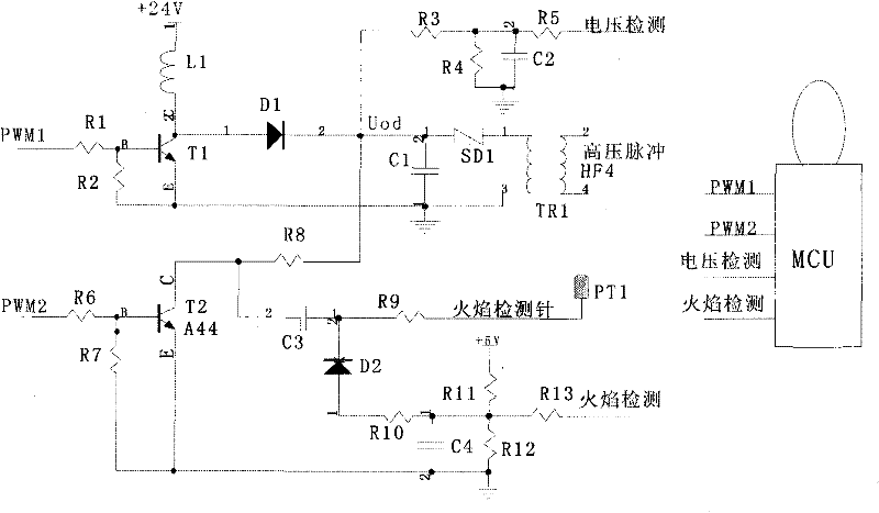
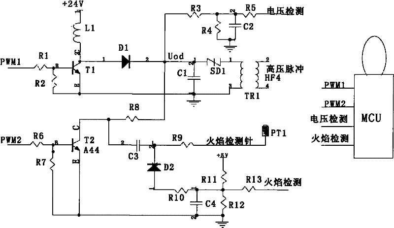
[0019] The flame ion current detection and pulse ignition circuit of the present invention will be further described in detail below in conjunction with the embodiment, the circuit schematic diagram is as follows figure 2 shown.

[0020] The selected values ​​of each component are: the resistance value of R1 is 4K7 ohms, the resistance value of R2 is 1K ohms, the resistance value of R3, R9, R11 is 1M ohms, the resistance value of R4 is 20K ohms, and the resistance value of R5, R6, R7, R13 10K ohms, R8 resistance is 200K ohms, R10 resistance is 470K ohms, R12 resistance is 4M7 ohms; C1 model is 1μF / 250V, C2 model is 103 / 50V, C3 model is 103 / 400V, C4 model is 104 / 50V; L1 model is 33mH; D1, D2 model is FR107; SD1 model is K2000G; T1, T2 model is A44; TR1 model is HF4.

[0021] The PWM1, R1, R2, T1, L1, D1, and C1 of the MCU form a boost circuit. When the output of PWM1 is high: T1 is saturated and turned on, and L1 is energized to store energy. When the output of PWM1 is low:...


PUM


Abstract

The invention relates to a flame ion current intensity detection and pulse ignition circuit, which is applied to the field of gas products such as gas water heaters, gas wall-mounted furnaces, gas air heating furnaces, gas boilers and the like. The circuit comprises a controllable inductive energy storage voltage boosting circuit, a voltage detection circuit, a constant-voltage, constant-frequency and constant-pulse-width power supply circuit and a flame ion current intensity detection and high-voltage pulse ignition circuit. A micro control unit (MCU) controls different duty ratio output of pulse width modulation (PWM)1 through a proportion integration differentiation (PID) algorithm, so the charging voltage of a capacitor C1 is stable during flame check, and the voltage is boosted to higher ignition trigger voltage during the ignition. A constant-voltage, constant-frequency and constant-pulse-width power supply is regulated by PWM2 through T2 and C3 and is used for flame ion current detection. During the flame ion current intensity detection, flame ion current is converted into voltage through R10, R11, R12, C3, C4 and the like, and the flame ion current intensity detection is realized through analog-digital (AD) sampling of the MCU. The problems that an alternating power supply of the traditional flame ion current for detection has large fluctuation, the flame ion current intensity fluctuation is caused, and the flame combustion state change requirement cannot be shown are solved. Simultaneously, flame check and ignition circuits are combined into one, and the cost is reduced.

Description

technical field [0001] The purpose of the present invention is to accurately control the voltage, frequency and pulse width of the pulse power supply used for the flame ion current size detection by a microcontroller (MCU), so that the detection of the flame ion current size can be accurately obtained by AD sampling of the MCU. , At the same time, the same pulse power supply can be used to obtain the medium voltage power supply circuit for the igniter. Background technique [0002] In the field of gas products such as gas water heaters, gas wall-hung boilers, gas hot blast stoves, and gas boilers, the efficiency of the gas combustion process and the level of exhaust emissions are related to the quality of the combustion conditions, and the quality of the combustion conditions is related to the gas and gas. The mixing ratio of the air is related, which directly reflects the change of the flame. Through the precise monitoring of the flame ion current, the mixing ratio of gas ...

Claims


Application Information

Patent Timeline
IPC IPC(8): F23Q3/00G01R19/00
Inventor 苏菠
Owner SHENZHEN ALLIED CONTROL SYSTEM CO LTD
Features
  • Generate Ideas
  • Intellectual Property
  • Life Sciences
  • Materials
  • Tech Scout
  • Unparalleled Data Quality
  • Higher Quality Content
  • 60% Fewer Hallucinations
Learn More