Reflective color filter
A color filter and reflective technology, applied in the direction of diffraction grating, optics, optical elements, etc., can solve the problems of unfavorable energy saving and environmental protection, low light energy utilization rate, etc., achieve simple structure, facilitate production, and improve light energy utilization rate Effect
- Summary
- Abstract
- Description
- Claims
- Application Information
AI Technical Summary
Problems solved by technology
Method used
Image
Examples
Embodiment 1
[0039] In this embodiment, the formation of a magenta grating structure is taken as an example for illustration.
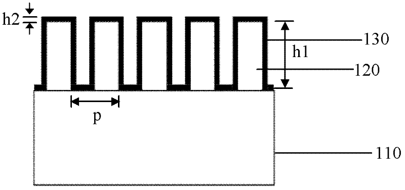
[0040] Please continue to see figure 2 , in this embodiment, the substrate 110 is a flexible material, specifically PET or PC. The dielectric grating 120 is a one-dimensional grating, and the material is PMMA. Metal layer 130 is aluminum. Further, the period p of the dielectric grating 120 is 200 nm, the duty ratio is F=0.5, and the thickness h1 is 280 nm. Metal layer thickness h2=30nm.
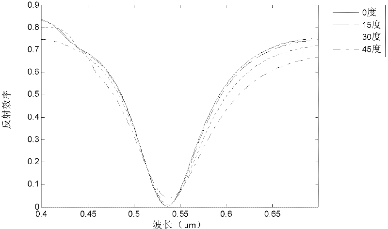
[0041] The reflection characteristics and angle tolerance of the filter were analyzed by rigorous coupled wave theory (RCWA). Due to the surface plasmon resonance phenomenon of the metal layer and the coupling effect of light and the surface periodic structure, part of the light is reflected, and the other part of the light is absorbed, and the transmittance is almost zero. TM polarized light is incident from the top of the structure at an angle ranging from 0° to 45°.
[...
Embodiment 2
[0045] This embodiment is to study the filter structures of different colors corresponding to different dielectric grating thicknesses. Except for the thickness of the dielectric grating, other parameters are consistent with those in Embodiment 1.
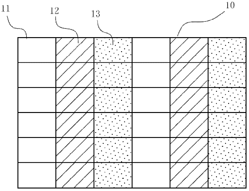
[0046] See Figure 5 , Figure 5 It is the relationship diagram between the reflection efficiency of TM light and the incident wavelength and the height h1 of the dielectric grating. When h1 changes between 0.23um and 0.33um, the position of the reflection valley changes. That is to say, by controlling the height of different dielectric gratings, the human eye will observe different colors under the incident condition of TM light. According to this characteristic, as long as dielectric grating structures with different thicknesses are designed on different pixels of the filter, the production of color filters can be realized. For example, for the grating structure corresponding to the magenta pixel, the thickness of the dielect...
Embodiment 3
[0048] Considering the errors in the process of fabricating the optical filter in the experiment, the effects of the occupation ratio of the dielectric grating and the thickness of the metal film on the reflection efficiency were observed.
[0049] First, observe the effect of the duty ratio of the dielectric grating on the reflection efficiency.
[0050] In the case that other parameters are consistent with those in the first embodiment, the duty ratio F of the dielectric grating is changed. Image 6 It is the relationship diagram of the reflection efficiency of TM light with the incident wavelength and the duty ratio of the dielectric grating.
[0051] When F changes between 0.45um and 0.55um, the position of the reflection valley changes, but the range of change is not large, basically still in the green light band (510nm-560nm). That is to say, under the error of 20% in the width ratio of the dielectric grating, the filtering effect of the color filter of the present inve...
PUM
 Abstract
Description
Claims
Application Information
 - R&D
- Intellectual Property
- Life Sciences
- Materials
- Tech Scout
- Unparalleled Data Quality
- Higher Quality Content
- 60% Fewer Hallucinations
Browse by: Latest US Patents, China's latest patents, Technical Efficacy Thesaurus, Application Domain, Technology Topic, Popular Technical Reports.
© 2025 PatSnap. All rights reserved.Legal|Privacy policy|Modern Slavery Act Transparency Statement|Sitemap|About US| Contact US: help@patsnap.com


