Burst light signal receiving apparatus

A receiving device and optical signal technology, which is applied in the field of optical communication, can solve the problems that cannot meet the requirements of burst optical signal reception, etc.

Active Publication Date: 2012-02-08
CHENGDU SUPERXON COMM TECH CO LTD
View PDF3 Cites 18 Cited by
  • Summary
  • Abstract
  • Description
  • Claims
  • Application Information

AI Technical Summary

Problems solved by technology

[0005] At present, there is no mature chip solution that can be applied to the reception of 10.3125Gbps burst optical signals, and the optical signal receiving chip in the 10G rate point-to-point optical communication system can only be used to receive continuous and stable optical signals, which cannot meet the needs of electrical and electronic engineers. Requirements of the 10 Gigabit Ethernet Passive Optical Network draft for the reception of burst optical signals

Method used


Image

  • Burst light signal receiving apparatus
  • Burst light signal receiving apparatus
  • Burst light signal receiving apparatus

Examples


Embodiment Construction

[0019] The technical solutions of the present invention will be further described below in conjunction with the accompanying drawings and through specific implementation methods.

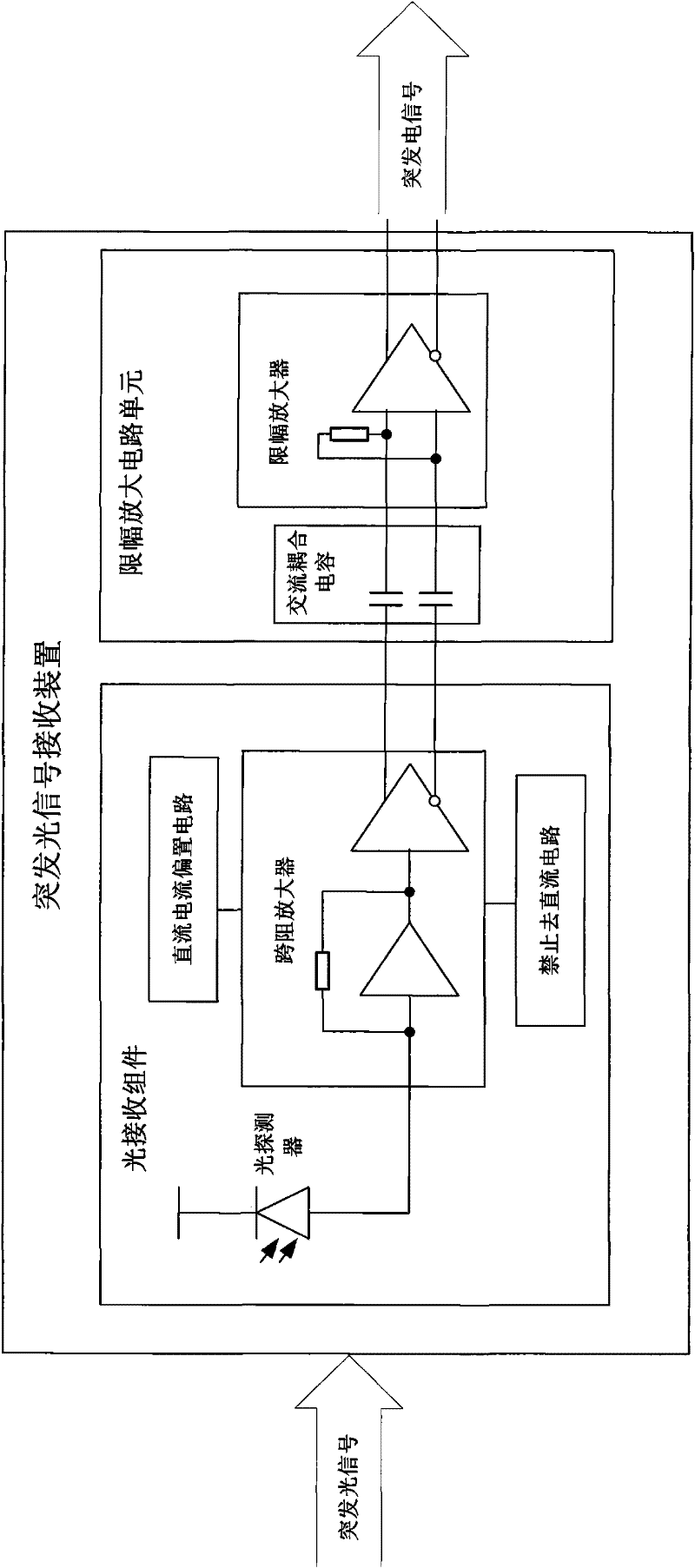
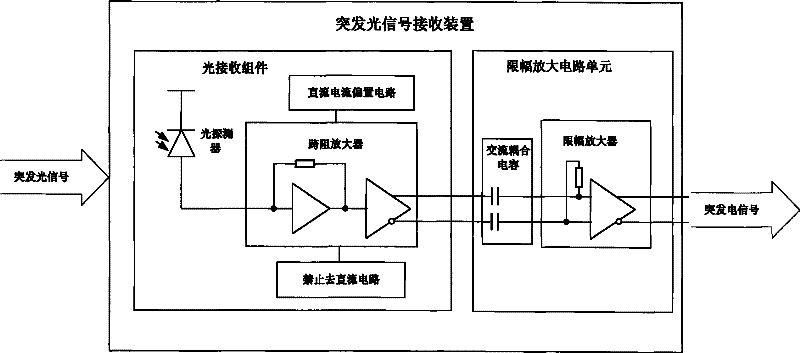
[0020] figure 1 It is a structural schematic diagram of the burst optical signal receiving device of the present invention. Such as figure 1 As shown, a burst signal receiving device includes a light receiving component and a limiting amplifier circuit unit, and the light receiving component further includes a photodetector, a transimpedance amplifier, a DC current bias circuit and a prohibiting DC circuit, and the limiting amplifier circuit The unit further includes a group of AC coupling capacitors and a limiting amplifier that can simultaneously amplify DC signals and AC signals.

[0021] The specific connection relationship is:

[0022] The output terminal of the photodetector is connected with the input terminal of the transimpedance amplifier, and is used for converting the received burst o...


PUM


Abstract

The invention discloses a burst light signal receiving apparatus which comprises: a light receiving assembly and an amplitude limit amplifier circuit unit. The light receiving assembly further comprises: a photo-detector, a transimpedance amplifier, a direct current reservation circuit 1 and a direct current offset circuit. The amplitude limit amplifier circuit unit further comprises: a group of alternating current coupling capacitors, an amplitude limit amplifier and a direct current reservation circuit 2. By using a technical scheme of the invention, the input burst light signals in a certain dynamic scope can be returned to the available burst light signals in a short time. The technical scheme of the invention can be used in a burst light signal receiver of a XENPAK passive optical network (10 GEPON).

Description

technical field [0001] The invention relates to the technical field of optical communication, in particular to a burst optical signal receiving device. Background technique [0002] Optical communication equipment usually needs to receive burst optical signals, which requires optical communication physical layer circuits to recover burst electrical signals in a short period of time, which brings difficulties to actual circuit design. [0003] This contradiction is particularly prominent in the burst optical signal receiver of the optical line terminal transceiver module of the 10 Gigabit Ethernet passive optical network (10GEPON). It is necessary to be able to receive the 10.3125Gbps burst optical signal from the optical network unit. [0004] Institute of Electrical and Electronics Engineers Draft for 10 Gigabit Ethernet Passive Optical Networks (IEEE P802.3av TM / D3.4, June 18, 2009) It is required that the optical line terminal optical module restores the 10.3125Gbps bu...

Claims


Application Information

Patent Timeline
Patent Type & Authority Applications(China)
IPC IPC(8): H04B10/06H04B10/69
CPCH04B10/693
Inventor 董轲
Owner CHENGDU SUPERXON COMM TECH CO LTD
Why Eureka
Try Eureka