Positron emission tomography ray detector

A ray detector and positron emission technology, which is applied in the field of medical devices, can solve the problems of small signal amplification, great performance changes, and cannot completely eliminate mutual interference, and achieve the effect of eliminating electromagnetic interference.

Inactive Publication Date: 2012-02-15
INST OF HIGH ENERGY PHYSICS CHINESE ACADEMY OF SCI
View PDF4 Cites 10 Cited by
  • Summary
  • Abstract
  • Description
  • Claims
  • Application Information

AI Technical Summary

Problems solved by technology

However, in this technical solution, the amplification circuit of the APD is still placed in the MRI magnetic field. Although it is located in the non-central area, it still cannot completely eliminate the mutual interference with the magnetic field; conditions vary widely

Method used


Image

  • Positron emission tomography ray detector
  • Positron emission tomography ray detector
  • Positron emission tomography ray detector

Examples


Embodiment Construction

[0023] The technical solutions in the embodiments of the present invention will be clearly and completely described below in conjunction with the accompanying drawings in the embodiments of the present invention. Obviously, the described embodiments are only some of the embodiments of the present invention, not all of them. Based on the embodiments of the present invention, all other embodiments obtained by persons of ordinary skill in the art without making creative efforts belong to the protection scope of the present invention.

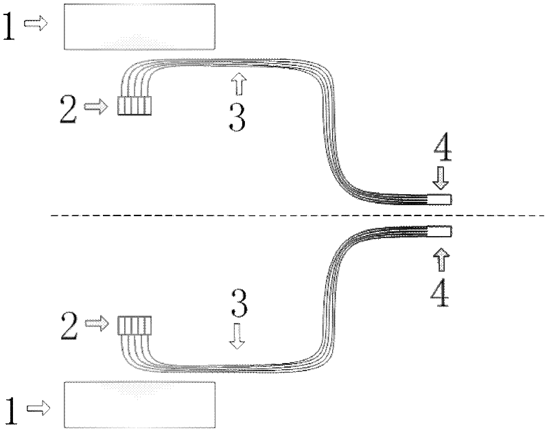
[0024] Embodiments of the present invention will be further described in detail below in conjunction with the accompanying drawings, as figure 1 Shown is a schematic structural diagram of a positron emission tomography ray detector provided by an embodiment of the present invention, figure 1 Including MRI main magnet 1, scintillator array 2, optical fiber or optical fiber bundle 3 and photomultiplier tube 4, wherein:

[0025] The scintillator arra...


PUM


Abstract

The invention discloses a positron emission tomography ray detector, which comprises a scintillator array, an optical fiber or optical fiber bundle and a photomultiplier tube, wherein the scintillator array consists of a plurality of independent scintillator units, works in an MRI (Magnetic Resonance Imaging) magnetic field, and is used for receiving radioactive rays and sending out flare light; one end of the optical fiber or optical fiber bundle is connected to the scintillator array, and receives and transmits the flare light sent out by the scintillator array; and the other end of the optical fiber or optical fiber bundle is connected with the photomultiplier tube, and the optical fiber or optical fiber bundle has the length so that the photomultiplier tube is positioned outside the MRI magnetic filed area and far away from the MRI magnetic field. By the structure, the combination of PET (Position-Emission Tomography) and MRI is simply realized, electromagnetic interference between the PET and the MRI is effectively removed, and a larger leeway is left on the integral mechanical structure.

Description

technical field [0001] The invention relates to the technical field of medical devices, in particular to a positron emission tomography radiation detector. Background technique [0002] At present, in the application of medical devices, the positron emission tomography (PET) system performs biological functional imaging by detecting the distribution of calibrated positron radioactive isotope biomolecules, and is often used in the early diagnosis of cancer and according to the biological morphology of cancerous tissues It is used to formulate treatment plans, and is also used for the diagnosis and treatment of heart disease and brain disease. The PET system is affected by physical factors in the imaging process, including the mean free path of positrons, the non-linearity of annihilation photons, etc., and its spatial resolution has a certain limit; while magnetic resonance imaging (MRI) has a good spatial resolution. The resolution capability can realize accurate three-dime...

Claims


Application Information

Patent Timeline
Patent Type & Authority Applications(China)
IPC IPC(8): A61B6/03A61B5/055
Inventor 魏龙唐浩辉李婷章志明李道武张天保王宝义魏存峰
Owner INST OF HIGH ENERGY PHYSICS CHINESE ACADEMY OF SCI
Why Eureka
Try Eureka