
Correcting system and method of sunlight reflecting device based on artificial light source

A reflection device and artificial light source technology, applied in the correction system field of solar emission devices, can solve the problems of unclear direction, unfavorable fast correction, increased cost, etc., and achieve the effect of overcoming high cost and avoiding amplification effect

Inactive Publication Date: 2012-02-15
ZHEJIANG UNIV +1
View PDF12 Cites 17 Cited by
  • Summary
  • Abstract
  • Description
  • Claims
  • Application Information

AI Technical Summary

Problems solved by technology

[0008] The spot acquisition device needs to stand on a high place and has a large area, which will greatly increase the cost; the image processing is complicated and time-consuming, which is not conducive to quick correction; when performing spot recognition, it is easily interfered by stray light; The device is far away, and the posture and position error of the heliostat are amplified by the distance, which may cause the spot to deviate from the spot acquisition device, and the direction is unknown, requiring a lot of search work; limited by the size of the spot acquisition device, the spot acquisition The number of devices may be large, and heliostats with different angles will form light spots of different shapes on the spot collection device, which also increases the difficulty of image processing and recognition; since multiple sets of data need to be collected when the sun is in different positions, it is necessary to Sampling within a large time span, thus making the entire correction period too long

Method used


Image

  • Correcting system and method of sunlight reflecting device based on artificial light source
  • Correcting system and method of sunlight reflecting device based on artificial light source
  • Correcting system and method of sunlight reflecting device based on artificial light source

Examples


Embodiment

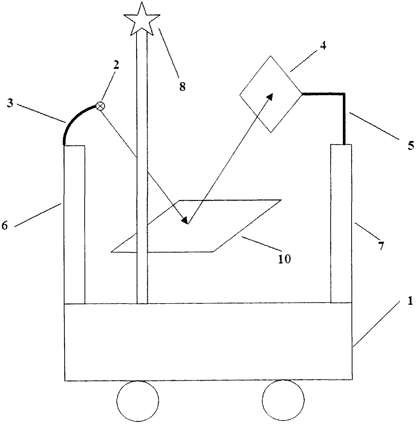
[0037] See Figure 1 to Figure 5 This embodiment provides a correction system for heliostats based on artificial light sources. The system includes: a free-running correction car 1, a laser emitting device 2 installed on the correction car, and a posture positioning system 3, which is used to receive The light-sensitive array receiving screen 4 of the heliostat 10 reflects light and its attitude positioning system 5, the laser emitting device supporting mechanism 6, the receiving screen supporting mechanism 7, the distance measuring positioning system and the data processing system 9.

[0038] The correction vehicle 1 can be controlled by one of the following methods: manual operation, manual remote control, and automatic control.

[0039] The laser emitting device 2 is selected from one of the following types: gas laser, solid laser or semiconductor laser, and can continuously change the laser output wavelength. For example, gas lasers can be helium-neon lasers, argon ion lasers, ...


PUM


Abstract

The invention discloses a correcting system and method of a sunlight reflecting device based on an artificial light source. The correcting system comprises a correcting vehicle capable of freely advancing, a laser emitting device installed on the correcting vehicle, a gesture locating system of the laser emitting device, a light-sensitive array receiving screen used for receiving rays reflected by the sunlight reflecting device, a gesture locating system of the light-sensitive array receiving screen, a laser emitting device supporting mechanism, a receiving screen supporting mechanism, a distance measuring and locating system and a data processing system. According to the invention, defects such as high cost, time spending, complexity in image processing, difficulty in searching light spots and the like of a sunlight combined solar light spot imaging correcting scheme are overcome, problems of high cost and searching of the correcting system such as a high-power tower-type artificial light source are solved, and the correction of the sunlight reflecting device is realized by using a method with low power, low cost and high precision.

Description

Technical field [0001] The present invention generally relates to the field of tower-type solar thermal power generation, and specifically relates to a correction system and a correction method of a daylight emitting device based on an artificial light source. Background technique [0002] The tower-type solar power generation system includes a receiver placed on a high tower (also called a receiving tower), a heliostat (for example, heliostat) laid on the ground around the high tower, a computer control system and a tracking drive mechanism. The computer control system controls the heliostat to automatically track the sun, and reflects the sun's rays to the receiver on the top of the receiving tower to boil the medium in it, and the steam generated thereby drives the turbine generator to generate electricity. Only when the heliostat accurately tracks the change of the sun's position can it ensure that the solar spot energy is accurately collected on the receiver, and the thermal...

Claims


Application Information

Patent Timeline
IPC IPC(8): G05D3/12
Inventor 李德文贾士博宓霄凌黄文君李江烨
Owner ZHEJIANG UNIV
Learn More