Light emitting diode (LED) dimming driving device, method and liquid crystal display

A dimming drive and dimming switch technology, applied in the direction of static indicators, instruments, electrical components, etc., can solve the problems of large noise and electromagnetic interference, unstable operation of PWM power supply system, etc., to avoid noise or electromagnetic interference, avoid Effects of Energy Loss and Noise

Active Publication Date: 2012-02-15
SHENZHEN CHINA STAR OPTOELECTRONICS TECH CO LTD
View PDF6 Cites 27 Cited by
  • Summary
  • Abstract
  • Description
  • Claims
  • Application Information

AI Technical Summary

Problems solved by technology

[0005] However, in the prior art, when the LEDs on all LED paths are turned on at the same time, a large amount of energy needs to be provided for the entire LED lighting system in a short period of time, which will generate relatively large noise and electromagnetic interference, and will also cause PWM power supply system job instability

Method used


Image

  • Light emitting diode (LED) dimming driving device, method and liquid crystal display
  • Light emitting diode (LED) dimming driving device, method and liquid crystal display
  • Light emitting diode (LED) dimming driving device, method and liquid crystal display

Examples


Embodiment Construction

[0039] It should be understood that the specific embodiments described here are only used to explain the present invention, not to limit the present invention.

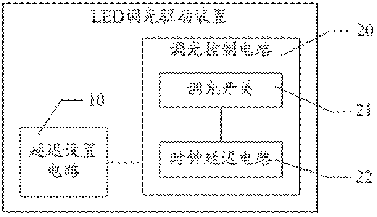
[0040] Such as figure 1 as shown, figure 1 It is a schematic structural diagram of an LED dimming driving device provided in Embodiment 1 of the present invention.

[0041] The LED dimming driving device provided by the embodiment of the present invention includes a delay setting circuit 10 and multiple dimming control circuits 20 , wherein the delay setting circuit 10 is used to set a different delay time for each dimming control circuit 20 . Each dimming control circuit 20 specifically includes:

[0042] The dimmer switch 21 is used to control the connection or blockage of one LED path;

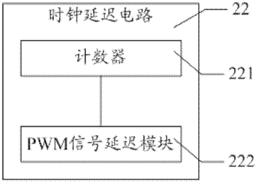
[0043] The clock delay circuit 22 is configured to receive the PWM signal and perform timing according to the delay time, and output the PWM signal to the dimming switch 21 when the delay time is completed.

[0044] In this emb...


PUM


Abstract

The invention provides a light emitting diode (LED) dimming driving device, an LED dimming driving method and a liquid crystal display. The LED dimming driving device comprises a plurality of routes of dimming control circuits, wherein each route of dimming control circuit specifically comprises a dimming switch. The LED dimming driving device is characterized by further comprising a delay setting circuit for setting different delay times for each route of dimming control circuit; and each route of dimming control circuit further specifically comprises a clock delay circuit for receiving a pulse-width modulation (PWM) signal, timing according to the delay time, and outputting the PWM signal to the dimming switch when the timing of the delay time is completed. The output of the PWM signal is controlled by different delay times to control the dimming switch to be turned on or off and effectively avoid the noise or the electromagnetic interference caused by the feeding of a mass of energy into an LED access since the dimming switch is simultaneously turned on by the PWM signal.

Description

technical field [0001] The invention relates to the technical field of LEDs, in particular to an LED dimming driving device, method and liquid crystal display. Background technique [0002] With the continuous development of LCD (Liquid Crystal Display, Liquid Crystal Display) technology, more and more manufacturers focus on LED (Light Emitting Diode, Light Emitting Diode) when selecting backlight sources, and apply LEDs as backlight sources to The advantages of LCD liquid crystal panels are becoming more and more prominent. It makes the LCD liquid crystal panel smaller in size, longer in service life, shorter in response time, lower in energy consumption, and its color performance is far better than that of traditional CCFL (Cold Cathode Fluorescent Lamp, cold cathode fluorescent light). [0003] With the development of LED technology, people have more and more stringent requirements for its dimming performance. In a traditional LED dimming driving device, a PWM (Pulse Wi...

Claims


Application Information

Patent Timeline
Patent Type & Authority Applications(China)
IPC IPC(8): G09G3/34G09G3/36
CPCG09G3/3406H05B45/46
Inventor 林柏伸廖良展杨翔
Owner SHENZHEN CHINA STAR OPTOELECTRONICS TECH CO LTD
Why Eureka
Try Eureka