Method for recirculating blast furnace gas, and associated device

A blast furnace gas recirculation technology, applied to blast furnaces, blast furnace details, blast furnace parts, etc., can solve problems such as flow control

Inactive Publication Date: 2012-02-15
ARCELORMITTAL INVESTIGACION Y DESARROLLO SL
View PDF8 Cites 5 Cited by
  • Summary
  • Abstract
  • Description
  • Claims
  • Application Information

AI Technical Summary

Problems solved by technology

[0016] The difficulty with this configuration is the control of the flow

Method used


Image

  • Method for recirculating blast furnace gas, and associated device
  • Method for recirculating blast furnace gas, and associated device
  • Method for recirculating blast furnace gas, and associated device

Examples


Embodiment Construction

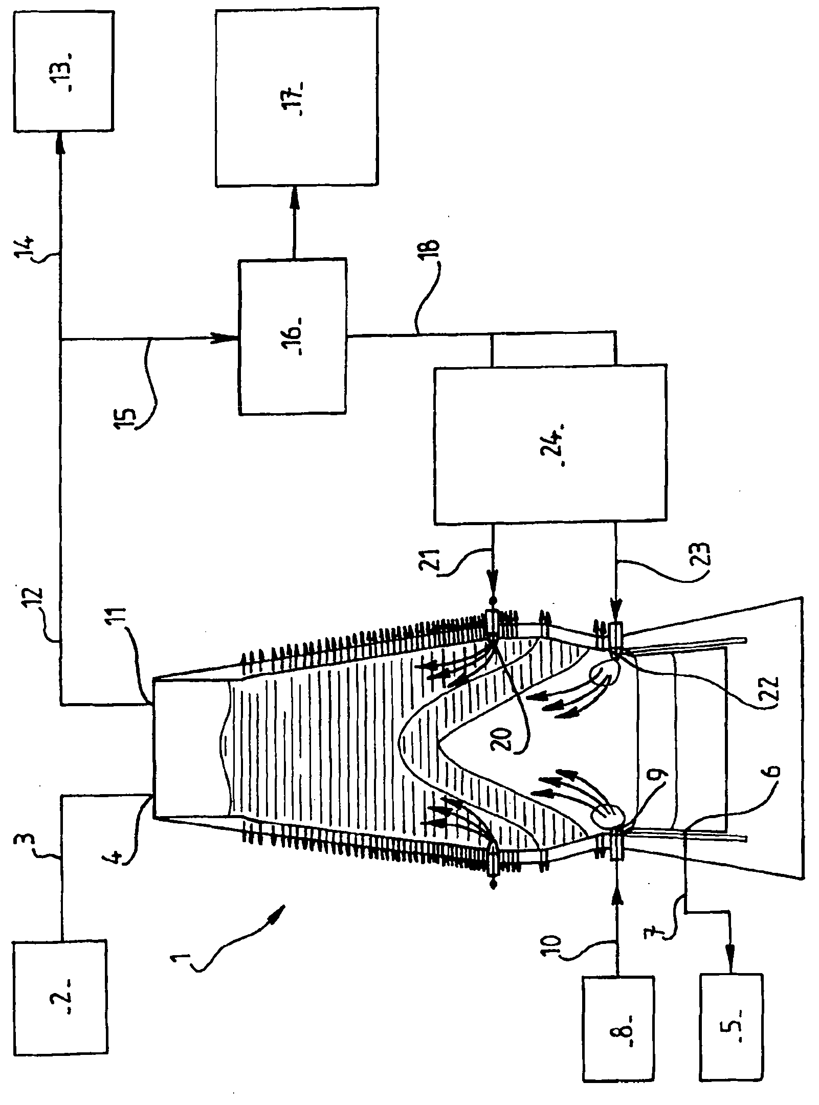
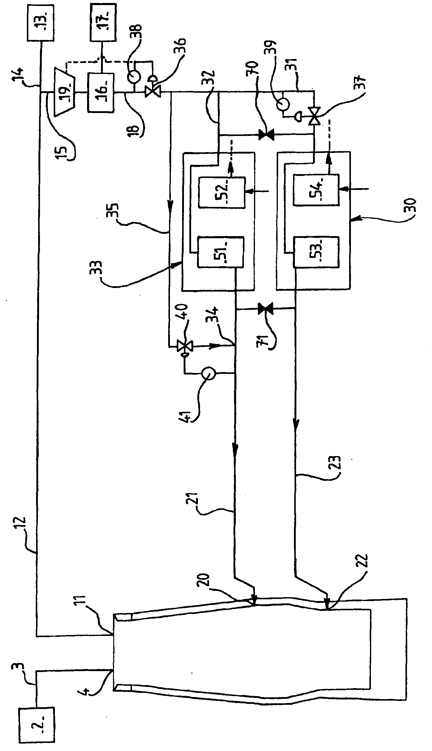
[0057] figure 1 , image 3 and Figure 4 Common elements of the devices bear the same designation. For reasons of simplicity, the injection of combustion-supporting fuel and the recovery of pig iron and slag are not included in the image 3 and Figure 4 shown above, but the steps present in the methods shown on these drawings are quite obvious.

[0058] refer to image 3 , blast furnace 1 is supplied with coke, iron ore, pellets and sinter 2 at point 4 via line 3 .

[0059] Top gas is recovered via line 12 at point 11 in the upper part of the blast furnace. A portion 13 of these top gases is conveyed via pipeline 14 to another plant on site. The other part is recycled in the blast furnace through line 15.

[0060] The part of the top gas for recirculation is passed in a compressor 19 and through a CO 2 Purifier 16 to purify CO 2 , such as an amine adsorption unit, a VPSA, a PSA, or one of these units combined with an additional refrigeration step. exist image 3 I...


PUM


Abstract

The invention mainly relates to a method for recirculating gas from a blast furnace in which at least part of the gases from the blast furnace are subjected to a CO2 purification step so as to create a gas that is rich in CO, which is then reinjected, at a first top injection point located above the base of the blast furnace and at a temperature of between 700 and 1000 DEG C, through a top injection line, and through a second bottom injection point at the base of the blast furnace at a temperature of between 1000 DEG C and 1300 DEG C through a bottom injection line, wherein the gases from the top and bottom injection lines are heated with reheaters from which gases are discharged at a temperature of between 1000 DEG C and 1300 DEG C. The method of the invention is essentially characterized in that part of the CO-rich gas (18) being discharged from the purification step is directly injected into the top injection line (21) via a cold gas injection line (35) so as to result in a temperature of between 700 and 1000 DEG C at the first top injection point (20), and in that the gas flow control in the bottom (22) and top (20) injection points takes place upstream from the reheater system (30,33; 45). The invention also relates to a device for implementing the abovementioned method.

Description

technical field [0001] The present invention relates to a process for the recycling of blast furnace gas in which at least a portion of the gas from the blast furnace undergoes a CO 2 A purification step to produce CO-enriched gas that is then injected into the blast furnace. The invention also relates to a device for carrying out the method. Background technique [0002] Blast furnaces are gas-liquid-solid convective chemical reactors whose main purpose is to produce pig iron, which is then converted into steel by reducing its carbon content. [0003] The blast furnace in the upper part is fed with solid matter, mainly sinters, pellets, iron ore and coke. A liquid consisting of pig iron and slag is discharged into the lower part of the blast furnace at the hearth level. [0004] The conversion of iron-containing charge (sinter, pellets and iron ore) to pig iron has traditionally been carried out by reducing gases (especially containing CO, H 2 and N 2 ) to reduce iron ...

Claims


Application Information

Patent Timeline
Patent Type & Authority Applications(China)
IPC IPC(8): C21B5/06
CPCC21B5/001C21B7/002C21B9/00Y02P10/122C21B2100/64C21B2100/282C21B5/06Y02P10/25Y02P10/32Y02E20/32
Inventor F·狄德隆Y·拉谢纳C·吉利翁J·博莱D·塞特
Owner ARCELORMITTAL INVESTIGACION Y DESARROLLO SL
Why Eureka
Try Eureka