Box type transformer station

A box-type substation and substation equipment technology, applied in distribution substations, substation/switch layout details, substation/switchgear cooling/ventilation, etc., can solve the problems of complex wiring and large substation occupation, and achieve simple wiring , save construction cost, and occupy a small space

Inactive Publication Date: 2012-02-22
BEIJING JOYO ELECTRIC CO LTD
View PDF7 Cites 7 Cited by
  • Summary
  • Abstract
  • Description
  • Claims
  • Application Information

AI Technical Summary

Problems solved by technology

[0005] The main purpose of the present invention is to disclose a substation to solve the problems of existing substations such as large footprint and complicated wiring

Method used


Image

  • Box type transformer station
  • Box type transformer station
  • Box type transformer station

Examples


Embodiment 1

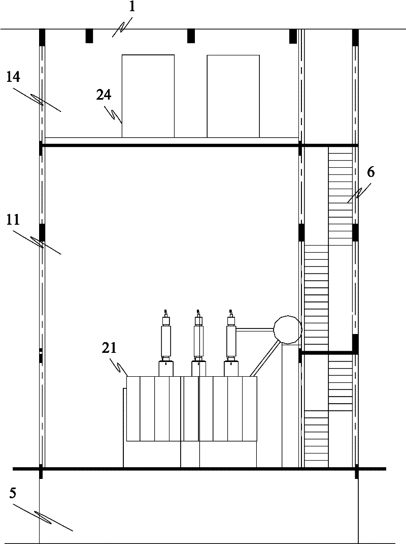
[0069] like Figure 1-5 As shown, the box-type substation of the present invention includes a three-layer box body 1, and the box body 1 is 14.5 meters long, 10.8 meters wide, and 15.5 meters high. Note: The low-voltage power distribution room does not refer to the low-voltage power distribution room, but refers to the medium-voltage 10KV lower than 220KV, which will not be repeated later) 12, of which the main transformer room 11 is 10 meters high and 10.8 meters wide, and the 10KV low Room 12 is 4 meters high and 10.8 meters wide. The overall length of main transformer room 11 and 10KV low distribution room 12 is 14.5 meters; the second floor of box body 1 is 220KV GIS room 13, which is set on 10KV low distribution room 12 , 7 meters high, 10.8 meters wide, and the length is consistent with the 10KV low distribution room 12. The 220KV GIS room is equipped with a 220KV high-voltage GIS; the third floor of the cabinet 1 is the main control room 14 and the capacitor room 15. O...

Embodiment 2

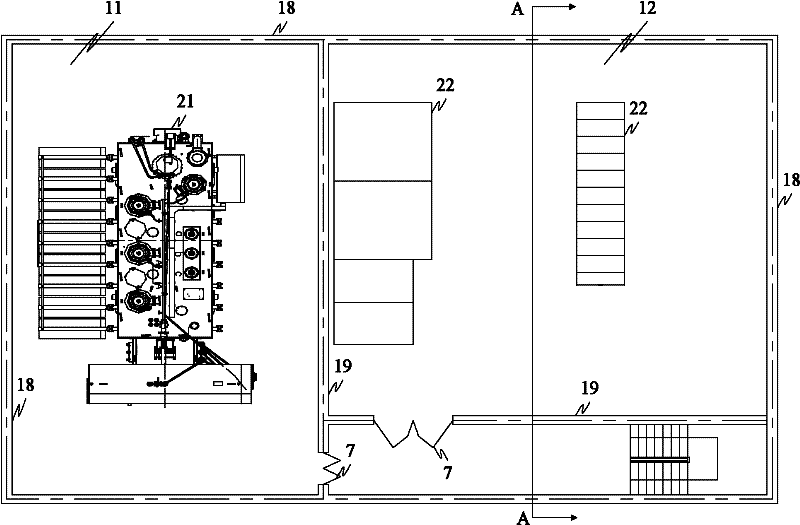
[0074] like Figure 6-10 As shown, the overall length of the box 1 is 14 meters (the length of the main transformer room 11 is 6 meters, and the length of the 220KV GIS room 13 is 8 meters), the width is 9 meters, and the height is 14.5 meters. The first floor is equipped with the main transformer room 11 and the 220KV GIS room. 13. The 10KV low distribution room 12 is located on the second floor. The 10KV low distribution room 12 is located on the 220KV GIS room 13. The main transformer room 11 is 10 meters high, the 220KV GIS room 13 is 6 meters high, and the 10KV low distribution room 12 is 4 meters high. The main control room 14 and capacitor room 15 are set on the third floor. The main control room 14 is set on the 10KV low distribution room 12, and the capacitor room 15 is set on the main transformer room 11. The capacitor room is 4.5m high, 9.0m wide, and 14.0m long. The overall structure and all the substation equipment (the electrical connection between the substation...

Embodiment 3

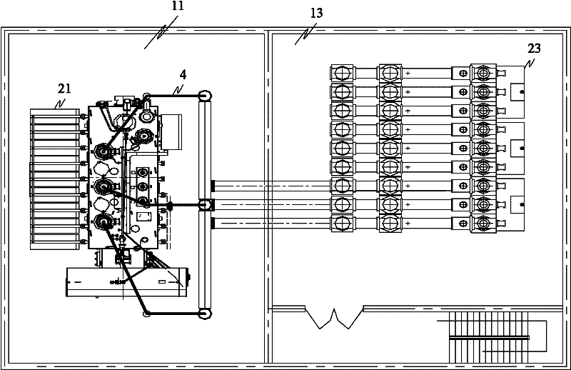
[0076] like Figure 11-15 As shown, as a modification of Embodiment 2, such as Figure 11-16 As shown, the main transformer 21 is composed of a transformer body 211 and a cooling group sheet 212. In order to better solve the heat dissipation problem of the main transformer 21, the transformer body 211 is placed in the main transformer room 11, and the cooling group sheet 212 is placed outside the main transformer room 11. , the length of the main change chamber is reduced relative to the second embodiment, so that the overall length of the casing 1 is reduced to 13 meters, as shown in the figure, wherein the length of the main change chamber 11 is 5 meters, and the length of the 220KV GIS chamber 13 is 8 meters, and other parts are consistent with the above-mentioned embodiment 2, and will not be repeated here.


PUM


Abstract

The invention relates to high voltage power transformation technology, and discloses a box type transformer station to solve problems of large land occupation, complex wiring and the like of a present transformer station. The box type transformer station comprises a case and a plurality of power transmission devices. An above ground part of the case is formed by a high voltage GIS (Gas Isolated Switchgear) chamber, a main transformation chamber, a middle voltage switching house, a master control chamber and a capacitor chamber. The transmission devices of each part of the case are electrically connected, wherein the main transformation chamber is at a bottom of the case, an underground part of a built-in main transformer of the main transformation chamber is divided as a pebble bed and an accident oil pool; an adjacent side of the main transformation chamber is provided with the high voltage GIS chamber or the middle voltage switching house; an adjacent chamber of the main transformation chamber is vertically superimposed with any two parts of rest three parts, and a top part of the adjacent chamber is side by side arranged with a case part above the main transformation chamber and shares a base plate with the latter.

Description

technical field [0001] The invention relates to a high-voltage power transformation technology, in particular to a box-type substation. Background technique [0002] In order to adapt to the development of the urbanization of the power system, the high-voltage substation needs to be miniaturized and can be produced in a factory. This is not only conducive to the selection of load center construction requirements in existing urban high-load density areas, but also conducive to the transformation of urban power grids, reducing the level of step-down, simplifying wiring, and greatly reducing power loss. [0003] As an urban distribution network, the existing high voltage levels in most areas of my country are 220, 110, 60KV, medium voltage 35, 10KV, low voltage 0.4KV, and the step-down level is 3 levels. For example: 220 / 110 / 10 / 0.4KV, 220 / 35 / 10 / 0.4KV, 220 / 60 / 10 / 0.4KV or level 4. For example: 220 / 110 / 35 / 10 / 0.4KV. At present, the biggest difficulty facing the development of my...

Claims


Application Information

Patent Timeline
Patent Type & Authority Applications(China)
IPC IPC(8): H02B7/06H02B1/04H02B1/46H02B1/56
Inventor 袁学恩李宗义李旭晗
Owner BEIJING JOYO ELECTRIC CO LTD
Why Eureka
Try Eureka