

Method for inhibiting overvoltage and overcurrent of resonant transformation circuit and resonant transformation circuit
A technology of resonant conversion and resonant circuit, applied in the direction of converting DC power input to DC power output, electrical components, adjusting electrical variables, etc., can solve the current stress and voltage stress rise, increase the output impedance of the resonant conversion circuit, and damage circuit devices. and other problems to achieve the effect of reducing voltage stress and current stress, suppressing overvoltage and overcurrent stress, and improving reliability
- Summary
- Abstract
- Description
- Claims
- Application Information
AI Technical Summary
Problems solved by technology
Method used
Image

Examples
Embodiment Construction
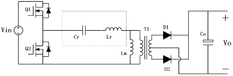
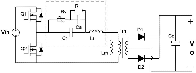
[0029] exist figure 2 The shown asymmetrical half-bridge resonant conversion circuit of Embodiment 1 of the present invention includes an inverter half-bridge composed of switching tubes Q1 and Q2, a transformer T1, a resonant capacitor Cr, a resonant inductance Lr, and a resonant capacitor connected in parallel with the resonant capacitor Cr. The branch circuit, the series circuit of the resonant capacitor Cr, the resonant inductance Lr and the primary winding of the transformer T1 is connected to the output end of the inverter half-bridge of the inverter bridge, and the resonant branch circuit includes the auxiliary resonant capacitor Ca, the varistor Rv and the discharge resistor R1 , the auxiliary resonant capacitor Ca is connected in series with the varistor Rv, and the bleeder resistor R1 is connected in parallel with the auxiliary resonant capacitor Ca. The circuit also includes a parallel resonant inductor Lm connected in parallel with the primary side of the transfor...
PUM
 Abstract
Description
Claims
Application Information