Pile sinking device and method for middle digging pulling-anchoring method pre-stressed centrifugal pipe pile (square pile)

A technology of prestressing and anchoring device, applied in sheet pile wall, construction, infrastructure engineering and other directions, can solve the problems of difficult quality assurance, high cost and high construction cost, and achieve the effect of ensuring safety, low cost and high efficiency

Active Publication Date: 2012-03-14
SHANGHAI CHENGDI CONSTR
View PDF7 Cites 5 Cited by
  • Summary
  • Abstract
  • Description
  • Claims
  • Application Information

AI Technical Summary

Problems solved by technology

3. Drilling and soil pressing method: that is, first use soil extraction equipment to make a hole on the original floor, and then press the pile into the hole. This method can be used in the northern region, because the water content in the soil is less, and the hole It can be formed, but in the Yangtze River Delta region in the south, the water content in the soil is high, the pilot hole cannot be formed, and the pile cannot be driven (pressed) in, and the pile is also prone to misalignment
When the piles are long, it is difficult to carry out drilling and soil extraction. At present, the deepest soil extraction can only reach about 30 meters; 4. Another pile foundation is the bored pile method: this meth

Method used


Image

  • Pile sinking device and method for middle digging pulling-anchoring method pre-stressed centrifugal pipe pile (square pile)
  • Pile sinking device and method for middle digging pulling-anchoring method pre-stressed centrifugal pipe pile (square pile)
  • Pile sinking device and method for middle digging pulling-anchoring method pre-stressed centrifugal pipe pile (square pile)

Examples


Embodiment Construction

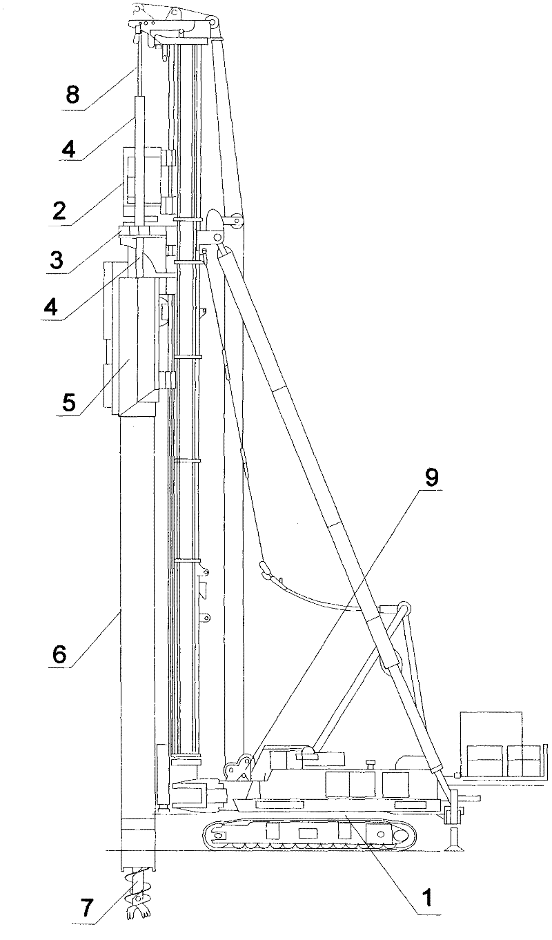
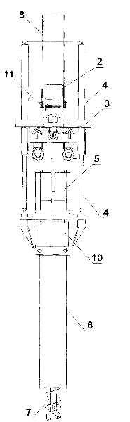
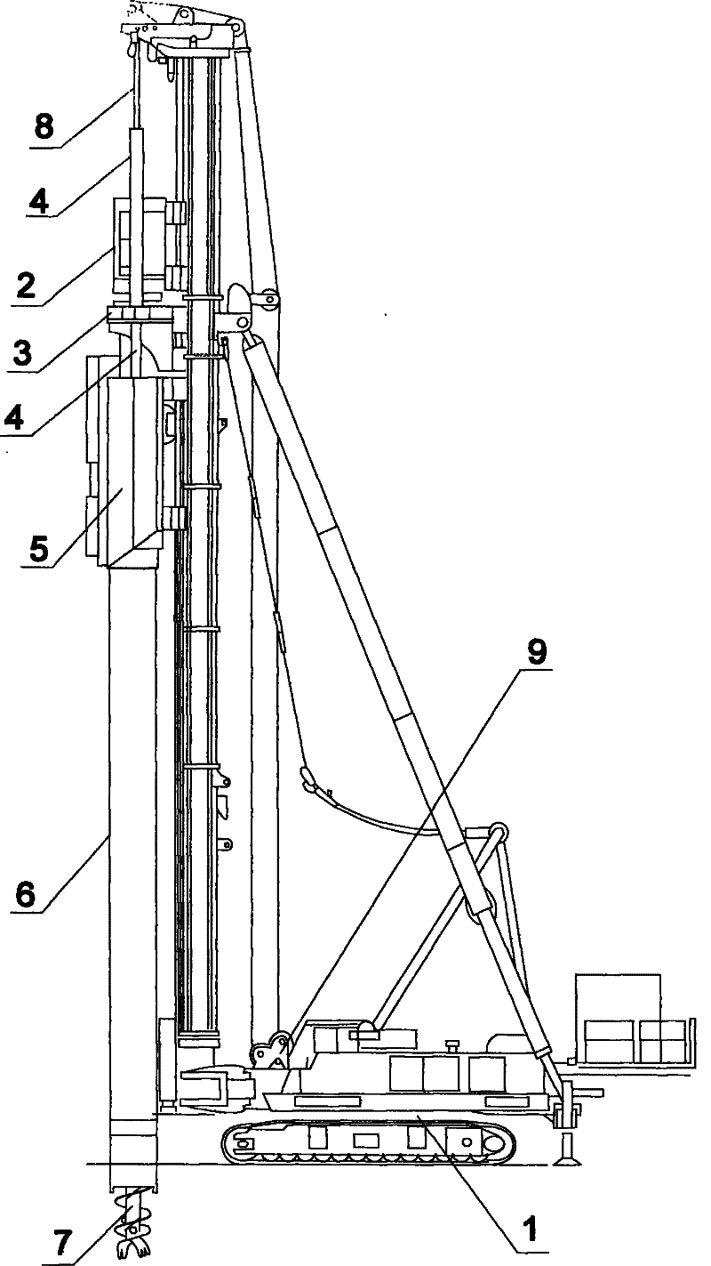
[0026] Such as Figure 1-2 Shown is a prestressed centrifugal tubular pile (square pile) pile sinking device with mid-digging and anchoring method, including a main engine 1, a winch 9 installed on the main engine, a power head 2, a hydraulic anchor pulling device 3, a press-in oil cylinder 4, Soil-borrowing box 5, pulley 11, steel wire rope 8, described power head 2, recovery box 5, oil pressure anchor device 3 are installed on the main engine 1, and described power head 2 upper end is equipped with pulley 11, and described pulley 11 is connected with a steel wire rope 8, the steel wire rope 8 is connected to the hoist 9 through the top of the host machine 1, the bottom of the power head 2 is connected to the soil-borrowing drill pipe 7, and the soil-borrowing drill pipe 7 is pulled through the oil pressure Anchor device 3, soil borrow box 5, pile cap 10, centrifugal pipe pile (square pile) 6 reach the bottom of the device, the oil pressure anchor device 3 is fixedly connecte...


PUM


Abstract

The invention discloses a pile sinking device for a middle digging pulling-anchoring method pre-stressed centrifugal pipe pile (square pile). The pile sinking device comprises a main machine, a windlass, a power head, an oil pressure pulling-anchoring device, a press-in oil tank, a soil sampling tank, a pulley and a steel wire rope, wherein the windlass is arranged on the main machine; the power head, a recovering tank and the oil pressure pulling-anchoring device are arranged on the main machine; the lower side of the power head is connected with a soil sampling drilling rod; and the soil sampling drilling rod passes through the oil pressure pulling-anchoring device, the soil sampling tank, a pile cap and the centrifugal pipe pile (square pile) to the bottom of the device. The invention further provides a pile sinking method for the middle digging pulling-anchoring method pre-stressed centrifugal pipe pile (square pile). The method comprises the following steps of: driving the soil sampling drilling rod to realize soil digging through the power head; realizing retraction of the press-in oil cylinder under the action of the road holding of the soil sampling drilling rod; and realizing pile pressing by digging soil and pressing the pile synchronously through the soil sampling drilling rod. The pile sinking device has the advantages of safety, reliability, low cost, high efficiency, no noise, no pollution, no soil compression, no slurry, environmental friendliness and the like.

Description

technical field [0001] The invention relates to a prestressed centrifugal pipe pile (square pile) pile sinking device and a pile sinking method of a mid-digging and pulling anchor method, which are mainly used in civil and industrial infrastructure construction, pipe piles (square piles) supporting buildings and various The load of the large-scale equipment foundation makes buildings and structures higher, so the depth of the pile driven into the soil and the diameter of the pile directly affect the bearing capacity of the pile. Background technique [0002] The pile sinking device and the pile sinking method of existing prestressed centrifugal pipe pile (square pile) are mostly to adopt hammering method and static pressure pile method, followed by drilling soil and pressing method and bored pile method. 1. Hammering method: When the diameter of the pile is large and there are no residents around, the hammering method can be used, but there is a lot of noise, black smoke and...

Claims


Application Information

Patent Timeline
IPC IPC(8): E02D7/28
Inventor 谢晓东卢寿根
Owner SHANGHAI CHENGDI CONSTR
Why Eureka
Try Eureka