
Solar energy collecting equipment and application thereof

A technology of solar concentrators and solar energy, applied in solar thermal power generation, solar thermal devices, photovoltaic modules, etc., can solve problems such as inconvenient maintenance, complicated manufacturing process, poor scalability, etc., and achieve enhanced overall stability and lateral stability The effect of high stability and spoke wheel structure strength

Inactive Publication Date: 2012-03-14
BEIJING TERASOLAR PHOTOTHERMAL TECH CO LTD
View PDF13 Cites 2 Cited by
  • Summary
  • Abstract
  • Description
  • Claims
  • Application Information

AI Technical Summary

Problems solved by technology

However, a major problem in these solar energy concentrating devices is that the weight of the structure itself and the impact of the wind will increase the mass of the structure, so that the system uses more materials and costs more
For general wind force, it will twist and deform the collection bar, thus reducing the efficiency of collection
If it is a strong wind and strong wind, the whole system will be destroyed. At the same time, these collection systems cannot be protected from rain and dust, and are inconvenient to maintain, which makes the cost and cost continue to rise.
In addition, the optical system of the current solar photovoltaic power generation system is complicated, the drive is complicated, and the cost is high; moreover, the problem of heat dissipation has become a major problem that cannot be avoided in high-power focused photovoltaic power generation. The cells are easily polluted and inconvenient to clean; the overall structure is resistant Poor wind performance, etc.
[0006] It can be seen from the above that the disadvantages of the existing technology are: the structural weight of the solar energy concentrating equipment increases due to the need to meet the requirements of wind resistance; in bad weather, the concentrating surface will be distorted and deformed, and it cannot prevent rain, dust, and hail. Inconvenient maintenance, high cost and cost, complex manufacturing process, poor scalability
In addition, because the existing technology is not connected as a whole, the reflectors are only connected at the left and right positions, not at the front and rear positions, so that a grid structure cannot be formed, and a large amount of reinforced concrete needs to be placed underground for fixing, resulting in high cost
When the concentrating equipment is used for solar photovoltaics, the existing technology has not yet seen a report that can solve the heat dissipation structure well

Method used


Image

  • Solar energy collecting equipment and application thereof
  • Solar energy collecting equipment and application thereof
  • Solar energy collecting equipment and application thereof

Examples


Embodiment Construction

[0044] Various embodiments of the present invention will be described in detail below in conjunction with the accompanying drawings.

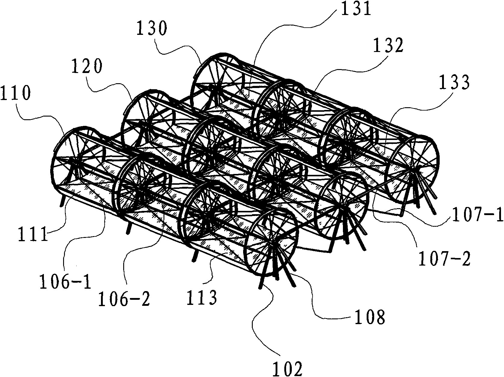
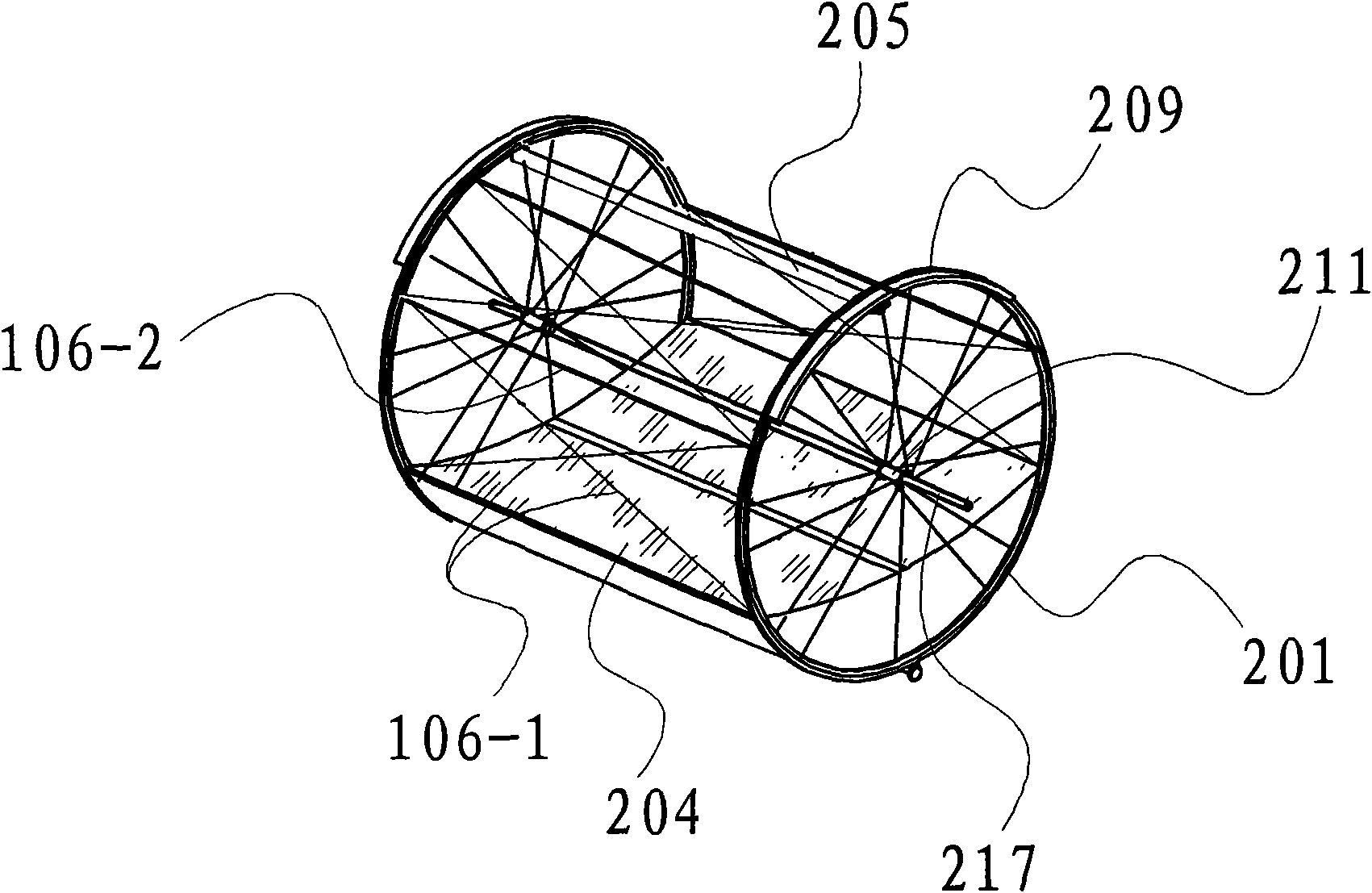
[0045] figure 1 is a three-dimensional schematic diagram of a solar energy concentration device according to an embodiment of the present invention. like figure 1 As shown, the solar concentrating device consists of three series series 110, 120, 130 connected in parallel. The series series 110 consists of aggregation units 111 , 112 and 113 . The series series 130 consists of aggregation units 131 , 132 and 133 . The series series 120 is likewise composed of three aggregation units, which are not numbered for simplicity of illustration. The aggregation unit is fixed and obliquely connected to each other through the oblique tension members 106-1 of the first connecting member 106, and the straight support members 106-2 are fixed and supported by each other to form a cylindrical structure, which greatly enhances the strength of the aggregatio...


PUM


Abstract

The invention disclosed solar energy collecting equipment. The solar energy collecting equipment comprises at least two spoke wheels, a central supporting shaft, a solar energy condenser, a receiver and a basic supporting structure, wherein the two spoke wheels comprise a first spoke wheel and a second spoke wheel which are arranged in opposite directions, are spaced in parallel, and are relatively fixed by a connecting piece; the central supporting shaft passes through the first spoke wheel and the second spoke wheel; the solar energy condenser is arranged between the first spoke wheel and the second spoke wheel and is fixed on rims of the first spoke wheel and the second spoke wheel; the receiver is fixed between the first spoke wheel and the second spoke wheel, is positioned on a focal line of the solar energy condenser, and is used for absorbing sunlight reflected by the condenser; the basic supporting structure is used for supporting the at least two spoke wheels; and the first spoke wheel, the second spoke wheel, the solar energy condenser and the receiver can be rotated together so as to track and concentrate sunrays. The solar energy collecting equipment is easy to manufacture, has standardized size and low field assembly workload, is suitable for modular production, is extremely convenient to assemble and maintain, can be operated in multiple kinds of adverse weather and is suitable for large-scale popularization and application.

Description

technical field [0001] The present invention relates to a solar energy concentrating device, in particular to a solar concentrating device adopting a spoke wheel device matrix and its application. Background technique [0002] As a clean and environmentally friendly energy source, solar energy has long been devoted to its development and utilization. Especially in recent years, due to the rising oil price, the improvement of environmental protection requirements, and the limitation of atmospheric carbon dioxide emissions, countries have worked harder to carry out research on solar energy utilization. [0003] Due to the low power density of solar radiation, in order to make full use of solar energy, it is a very important technology in solar energy utilization to track the position changes of sunlight and convert the light into heat and electricity. At present, a variety of solar energy concentrating devices with different concentrating methods are in use. Overall, the foc...

Claims


Application Information

Patent Timeline
Patent Type & Authority Applications(China)
IPC IPC(8): F24J2/46H02N6/00H02S40/22
CPCY02E10/40Y02E10/52
Inventor 刘阳
Owner BEIJING TERASOLAR PHOTOTHERMAL TECH CO LTD
Learn More