Real-time partial zero compensation optical aspheric surface profile detection method

A technology of zero position compensation and surface shape detection, which is applied in the direction of using optical devices, measuring devices, instruments, etc., can solve the problems of small detection dynamic range and achieve the effects of improving dynamic range, accurate detection and simple method

Inactive Publication Date: 2012-03-14
XIAN TECHNOLOGICAL UNIV
View PDF4 Cites 39 Cited by
  • Summary
  • Abstract
  • Description
  • Claims
  • Application Information

AI Technical Summary

Problems solved by technology

[0004] The present invention provides a real-time partial zero-position compensation optical aspheric sur

Method used


Image

  • Real-time partial zero compensation optical aspheric surface profile detection method
  • Real-time partial zero compensation optical aspheric surface profile detection method
  • Real-time partial zero compensation optical aspheric surface profile detection method

Examples


Embodiment 1

[0026] Embodiment 1: The process of using the present invention to detect the rotationally symmetrical secondary concave aspheric surface type is as follows:

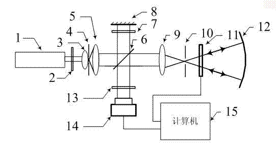
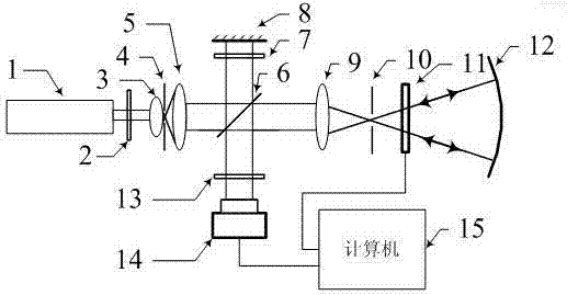
[0027] 1) After beam expansion and collimation, the light emitted from the He-Ne laser is used as an illumination source, and a standard Tieman-Green interference optical path is built. The light in one optical arm is reflected by a standard plane mirror and used as a reference light. The aspheric surface is placed in another optical arm, and the reflected light is used as the object light.

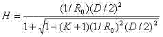
[0028]2) According to the characteristic parameters of the aspheric surface to be measured: quadric surface constant K , Vertex curvature radius R 0 , polynomial coefficient A n , Aspheric diameter D , find the edge sagittal height of the aspheric surface H ,

[0029]

[0030] Then find the best matching spherical radius of the aspheric surface to be tested R , the best matching sphere refers to the sphere that minimizes...

Embodiment 2

[0040] Embodiment 2: The process of utilizing the present invention to detect the surface type of a rotationally symmetric quadratic concave aspheric surface is as follows:

[0041] The difference from Example 1 is step 7), in step 7), the phase modulation range of the selected liquid crystal spatial light modulator is less than 2p: so the phase function y i = y CGH +( i -1)p / 4, i =1, 2, 3, 4, take the modulus of 2p, and then perform binary quantization to obtain the corresponding calculated holograms respectively; then load the holograms on the liquid crystal spatial light modulator in turn, and obtain the +1 order diffraction of the hologram The light wave is used as the illumination light wave, and the light wave returned from the aspheric surface to be tested passes through the hologram to take the +1 order diffracted light, which interferes with the plane reference light wave, and the CCD camera records four phase-shifted interferograms in sequence I i .

[0042] T...


PUM


Abstract

The invention relates to the filed of optical aspheric surface accurate measurement, in particular to a real-time partial zero compensation optical aspheric surface profile detection method. Current zero measurement method only can measure a dynamic range of several wavelengths so that the dynamic range of detection is small. The dynamic range of measurement in the invention is determined by three parts, consisting of a compensation lens, a phase function yGGH which corresponds to a computer generated hologram kinoform loaded by an LCSLM (Liquid Crystal Spatial light Modulator), and a residual phase function yRES. According to the real-time partial zero compensation optical aspheric surface profile detection method, a partial zero compensation technology is adopted, the LCSLM loaded with the computer generated hologram is served as a partial zero compensation element, and a convergent lens playing a role in compensation and an interference fringe analyzing technology are combined, therefore, the dynamic range of measurement is greatly improved, and detection to the profiles of the large aspheric surfaces can be implemented.

Description

technical field [0001] The invention relates to the field of precise measurement of optical aspheric surfaces, in particular to a real-time partial zero compensation optical aspheric surface type detection method. Background technique [0002] While improving the image quality of the optical system, the aspheric optical element simplifies the structure of the system, so it is applied in more and more systems. In order to quantitatively detect the aspheric surface structure, the zero compensation interferometry technology mainly adopts the calculation hologram (CGH) as the zero compensation element at present. In order to obtain surface information accurately, phase-shifting interference is introduced. However, phase shifting is achieved either by using a Fizeau phase-shifting interferometer as part of the test setup, or by introducing an additional phase-shifting device separately, resulting in expensive testing. In addition, computational holograms need to use ion beam pr...

Claims


Application Information

Patent Timeline
IPC IPC(8): G01B11/24
Inventor 韩军郭荣礼路绍军段存丽郑婷
Owner XIAN TECHNOLOGICAL UNIV
Why Eureka
Try Eureka