
Method for clamping crystal by adopting heat emission heat sink in laser diode end-pumped solid-state laser

A technology of laser diodes and solid-state lasers, applied to lasers, laser components, laser components, etc., can solve problems such as uneven distribution, affecting the quality of output light, and bursting

Inactive Publication Date: 2012-03-14
刘海强
View PDF0 Cites 5 Cited by
  • Summary
  • Abstract
  • Description
  • Claims
  • Application Information

AI Technical Summary

Problems solved by technology

When two heat sinks are used to clamp the round rod-shaped laser crystal, due to the uneven distribution of contact heat conduction between the crystal rod and the heat sink, the heat loss is transmitted at different circumferential angles according to different heat flows, resulting in an uneven distribution of the temperature field in the crystal. Axisymmetric, so that thermal effects such as thermal lens effect, thermal stress birefringence effect and end face deformation effect are non-axisymmetric, which affects the quality of output light, and even causes the crystal rod to burst due to uneven heating

Method used


Image

  • Method for clamping crystal by adopting heat emission heat sink in laser diode end-pumped solid-state laser
  • Method for clamping crystal by adopting heat emission heat sink in laser diode end-pumped solid-state laser
  • Method for clamping crystal by adopting heat emission heat sink in laser diode end-pumped solid-state laser

Examples


Embodiment 1

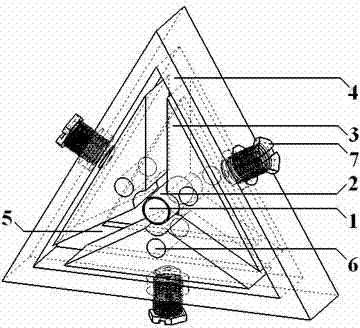
[0016] like figure 1 As shown, for the circular laser crystal 1, the clamping method of three metal heat sinks 3 is adopted, the metal frame 4 is triangular, and there is a metal boss 5 on the metal frame 4, and the metal boss 5 and the metal frame 4 are integral structures, which can be The axial rotation of the laser crystal 1 during clamping is prevented.

[0017] Taking the diameter of the circular laser crystal 1 as 4 mm and the length of 10 mm as an example, connect the vertices of the end face of a whole heat sink to the center point of the surface where it is located. Holes, using the wire cutting method to cut the heat sink along the connecting line into a single piece of metal heat sink 3 with a corresponding number of pieces.

[0018] The width of each side of the metal frame 4 and the width of each metal heat sink 3 is 20 mm, and there is a top wire 7 at the center of each side, and each metal heat sink 3 is fixedly connected to the metal frame 4 through the top w...

Embodiment 2

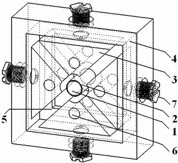
[0022] like figure 2 As shown, the structure of this embodiment is basically the same as that of Embodiment 1, the difference is that the clamping method of four metal heat sinks 3 is adopted, and the metal frame 4 is square. The four metal heat sinks are more evenly stressed and have better thermal conductivity.

Embodiment 3

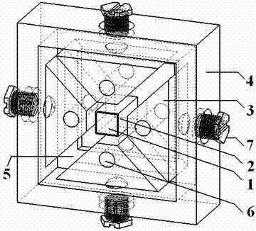
[0024] like image 3 As shown, since the laser crystal 1 has a quadrangular structure, the clamping method of four heat sinks is adopted, and the metal frame 4 is square. The metal frame 4 is provided with a metal boss 5, and the metal boss 5 and the metal frame 4 are integral structures, which can prevent the laser crystal 1 from rotating axially during the clamping process.

[0025] Taking the quadrangular laser crystal 1 with a length and width of 20 mm and a thickness of 10 mm as an example, connect the vertices of the end face of the entire heat sink block to the center point of the face where it is located, and use the wire cutting method to cut the heat sink along the connection line as Four triangular prisms, cut one corner of each triangular prism to obtain a plane parallel to the sides of the original quadrangular prism and the size of the side of the crystal rod 1, and process the clamping surface of each metal heat sink 3 to make it rough is 2 microns.

[0026] T...


PUM


Abstract

The invention relates to a method for clamping a crystal by adopting a heat emission heat sink in a laser diode end-pumped solid-state laser. A packing indium foil of a laser crystal bar, metal heat sinks, a metal framework and jackscrews on the top of the metal framework are adopted in the clamping method, wherein a circulating water current channel is arranged on each metal heat sink; the clamping method is characterized in that the number of the metal heat sinks is no less than 3, the metal heat sinks are used for symmetrically clamping the crystals of the laser, and a clamping surface of each metal heat sink is wedged with the contact surface of the crystal of the laser; the metal framework is polygonal; the number of sides of the polygon is dependent on the number of the metal heat sink; each metal heat sink is fixedly connected with each side of the metal framework by the jackscrew; and the crystals of the laser are clamped by using the jackscrews. The temperature of the crystals of the laser uniformly varies along the surface; and the maximum value of the temperature decreases, which is helpful to the axial symmetry of heating effect of the crystals and the prevention of breakage due to overhigh local temperature of the end surfaces of the crystals.

Description

technical field [0001] The invention belongs to the field of laser technology, and relates to a clamping method for a heat sink of a laser diode end-pumped solid-state laser crystal, in particular to a clamping method of a heat sink of a laser diode end-pumped solid-state laser crystal. Background technique [0002] In diode end-pumped solid-state lasers, the laser crystal is usually wrapped by a thermal interface material (such as indium foil) and then clamped by a metal heat sink. The thickness of the thermal interface material is generally between tens to hundreds of microns. Since the thermal conductivity of the metal heat sink is much greater than that of the crystal, the heat sink can be kept at a constant temperature (for example, 20°C) as a whole by circulating water flow or TEC heat dissipation. In practice, an absolutely smooth surface does not exist, and the surface of the crystal and the surface of the heat sink have a certain roughness, so that there is a certai...

Claims


Application Information

Patent Timeline
IPC IPC(8): H01S3/042H01S3/02
Inventor 刘海强王石语
Owner 刘海强
Learn More